Interbody fusion device with anti-rotation features

a technology of interbody fusion and features, which is applied in the field of interbody fusion devices, can solve the problems of limiting or even preventing bone healing, difficult quality control, and high cost of twisting each individual tooth to create a locking thread, and achieves the effect of increasing resistance to unscrewing

Inactive Publication Date: 2007-03-20
WARSAW ORTHOPEDIC INC
View PDF24 Cites 39 Cited by
  • Summary
  • Abstract
  • Description
  • Claims
  • Application Information

AI Technical Summary

Benefits of technology

[0005]The present invention provides an interbody fusion device having structures to limit rotation in at least one direction after the device is implanted between two bony structures. In one aspect of the present invention, an improved interbody fusion device is provided with an anti-rotation thread cut out. In this aspect, the fusion device includes a body portion with a thread pattern defined thereon. The thread pattern extends at least partially from a first end to an opposite second end. At least one thread is interrupted by a thread cut out on a trailing edge of the thread. The thread cut out includes an undercut portion extending beneath the outer surface of the interrupted thread to create a barb. When force is applied, attempting to unscrew the device, material from the thread path may be urged into the undercut area and retained there to resist accidental unscrewing. Preferably, the thread cut out also creates a relatively sharp pointed barb. The pointed barb may tend to impale bone tissue, further increasing resistance to unscrewing.

Problems solved by technology

Motion around the implant can restrict or even prevent bone healing.
While such interrupted locking threads may be satisfactory in preventing unscrewing, the manufacturing process of twisting each of the individual teeth to create a locking thread may be costly and difficult to control from a quality aspect.

Method used


Image

  • Interbody fusion device with anti-rotation features
  • Interbody fusion device with anti-rotation features
  • Interbody fusion device with anti-rotation features

Examples


Embodiment Construction

[0027]For the purposes of promoting an understanding of the principles of the invention, reference will now be made to the embodiments illustrated in the drawings and specific language will be used to describe the same. It will nevertheless be understood that no limitation of the scope of the invention is thereby intended, and such alterations and further modifications in the illustrated device, and such further applications of the principles of the invention as illustrated therein being contemplated as would normally occur to one skilled in the art to which the invention relates.

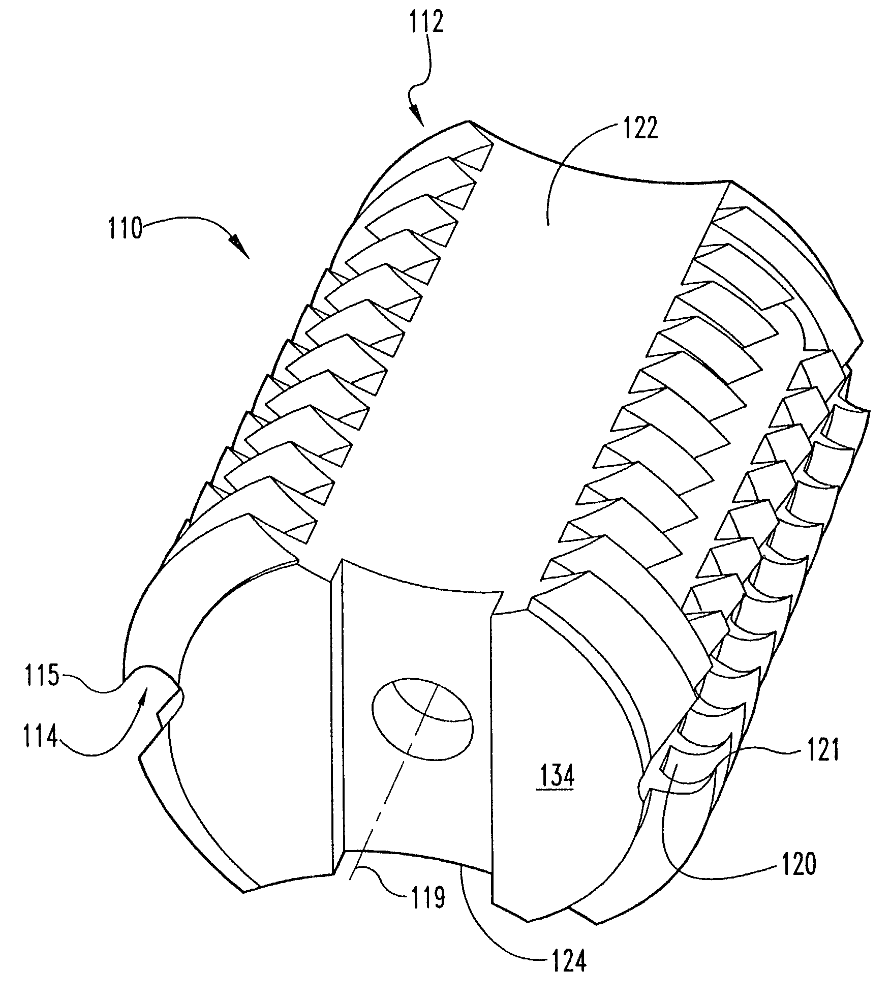
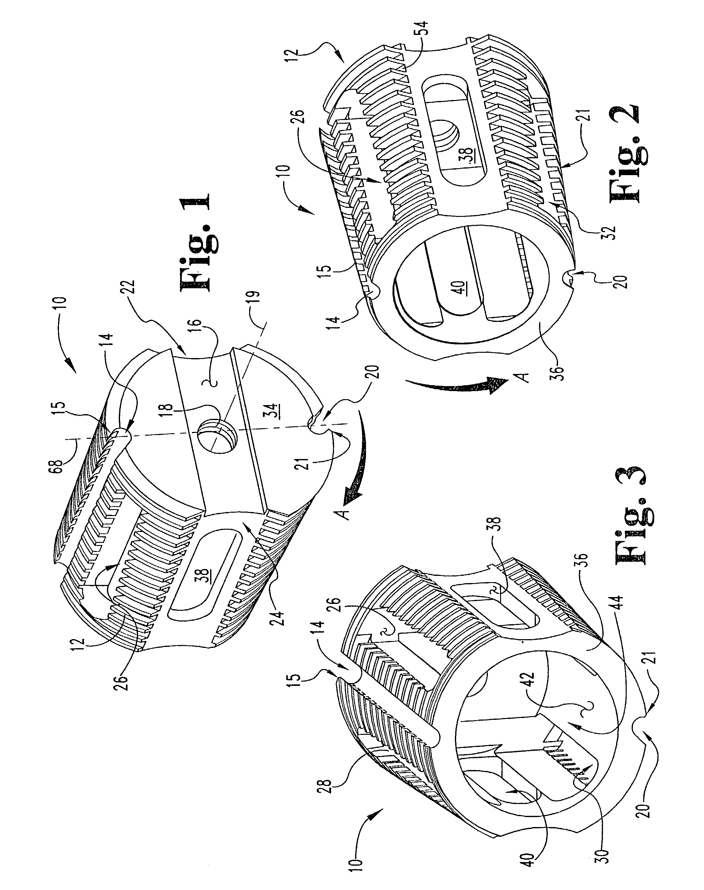
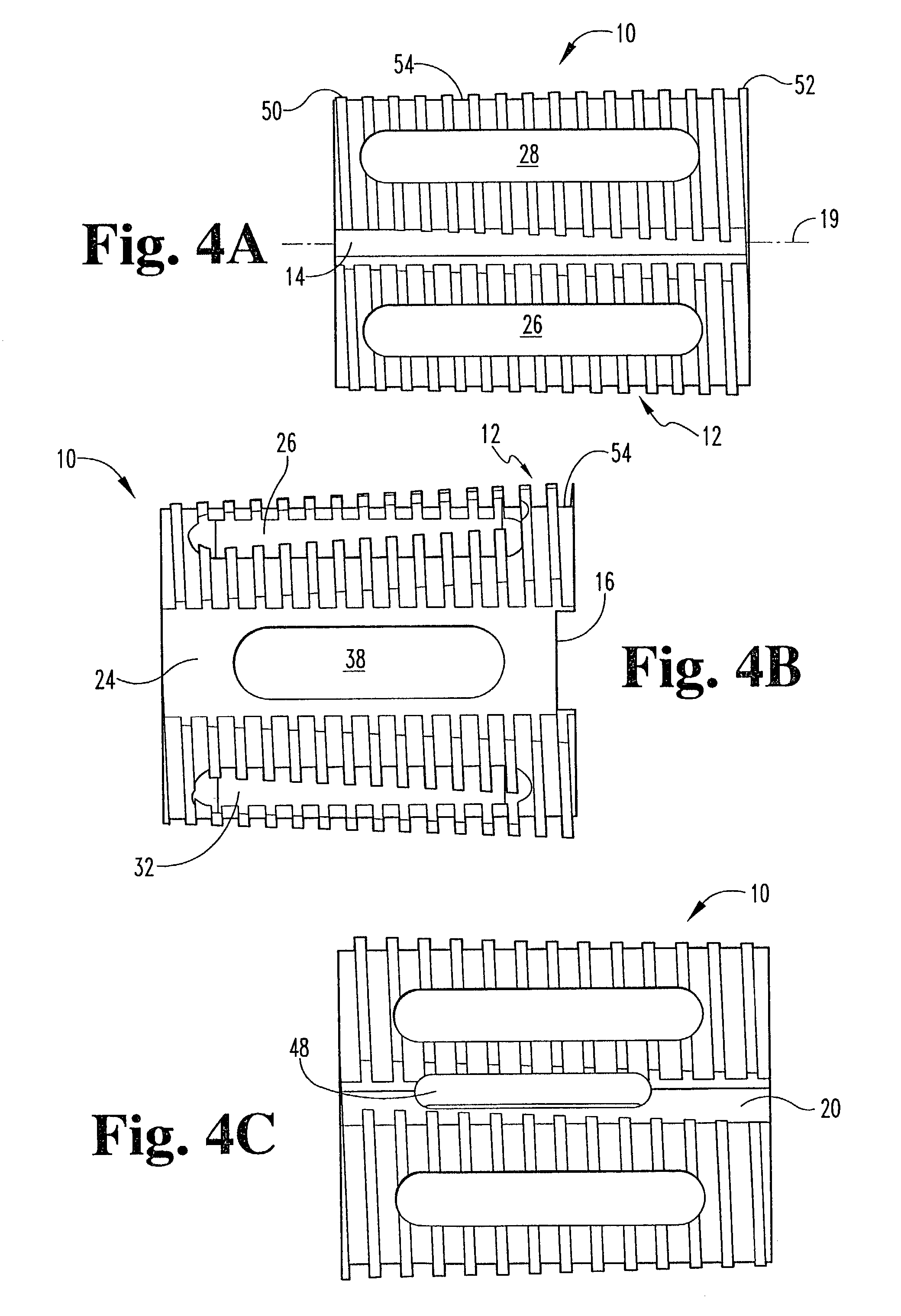
[0028]Referring now to FIGS. 1 through 6, there is shown an improved interbody fusion device or cage 10 according to the present invention. Device 10 comprises an elongated body having an outer surface 54 extended between a first end 34 and a second end 36 and defining a longitudinal axis 19. End 34 is referred to as the proximal end since it is the end closest to the user as the device is being inserted in...


PUM


Abstract

An improved interbody fusion device incorporating anti-rotation features to inhibit accidental screwing or unscrewing of the fusion device in an intervertebral disc space. One such feature is a thread pattern having a crest diameter that increasingly tapers from a smaller diameter at the insertion end to a larger diameter at the opposite end making further advancement of the thread into the bone more difficult. Another feature is a thread cut out on the trailing edge of the thread, creating a barb which has a tendency to inhibit unscrewing. These features may be used alone or in combination for an improved interbody fusion device.

Description

CROSS REFERENCE TO RELATED APPLICATIONS[0001]The present application is a divisional of U.S. patent application Ser. No. 09 / 498,050 filed on Feb. 4, 2000 and to be granted as U.S. Pat. No. 6,436,139, which claims the benefit of the filing date of provisional patent application No. 60 / 118,939, filed on Feb. 4, 1999.BACKGROUND OF THE INVENTION[0002]The present invention relates to interbody fusion devices disposed between two bony structures to maintain spacing therebetween and promote bony fusion. More specifically, the present invention relates to interbody fusion devices having threads or other structures defined on the outer surface to limit movement of the device between the bony structures. Most often, such devices find application in the spine for fusing adjacent vertebrae.[0003]It is well known to utilize an artificial spinal fusion implant to be inserted in the space between two adjacent vertebra after removal of a damaged spinal disc or portion thereof. Common forms of such ...

Claims


Application Information

Patent Timeline
Patent Type & Authority Patents(United States)
IPC IPC(8): A61F2/44A61B17/56A61F2/28A61F2/30A61F2/46
CPCA61F2/446A61F2002/30828A61F2002/30827A61F2002/30861A61F2002/30868A61F2002/30873A61F2002/30874A61F2002/4475A61F2002/448A61F2/442A61F2/4611A61F2002/2835A61F2002/30774A61F2002/30777A61F2002/30779A61F2002/30785A61F2002/30787A61F2002/30858A61F2002/30593
Inventor SHAPIRO, DAVID E.MCGAHAN, THOMAS VICTOR
Owner WARSAW ORTHOPEDIC INC
Why Eureka
Try Eureka