Constrained acetabular insert for total hip arthroplasty

a technology of acetabular insert and total hip arthroplasty, which is applied in the field of prosthesis, can solve the problems of debilitating and extremely painful dislocations, excessive deformation of liner, and inability to fully fully fully recover, so as to reduce the size of restricted opening and inhibit the separation of liner

Inactive Publication Date: 2007-03-20
ORTHOPAEDIC RES INST
View PDF2 Cites 56 Cited by
  • Summary
  • Abstract
  • Description
  • Claims
  • Application Information

AI Technical Summary

Benefits of technology

[0010]The present invention also contemplates a novel method for using the novel hip prosthesis. The shell is attached to a patient's pelvis, and the liner is inserted in the shell. The retainer ring is positioned over the patient's femur and behind the ball of the femur. The ball of the femur is forced into the liner expanding the expandable portion as the ball of the femur moves past the restricted opening of the liner. The retainer ring is attached to the shell, so that it engages the liner to inhibit expansion of the expandable portion and inhibit separation of the liner from the shell. Preferably, the liner is inserted into the shell by pushing on the positioning flanges, and the ring is snapably attached to the shell. Further, the expandable portion is preferably elastically expanded, and the retainer ring engages the liner to reduce the size of the restricted opening.

Problems solved by technology

Such dislocations are debilitating and extremely painful.
Some types of hip prostheses are more prone to dislocations, so that the patients must undergo additional surgery to replace or repair the prostheses.
The dislocations typically occur because the liner is not securely held in the shell the liner does not engage enough of the ball of the femur, and / or the liner is too easily deformed.

Method used


Image

  • Constrained acetabular insert for total hip arthroplasty
  • Constrained acetabular insert for total hip arthroplasty
  • Constrained acetabular insert for total hip arthroplasty

Examples


Embodiment Construction

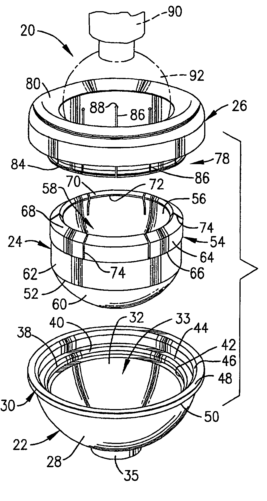
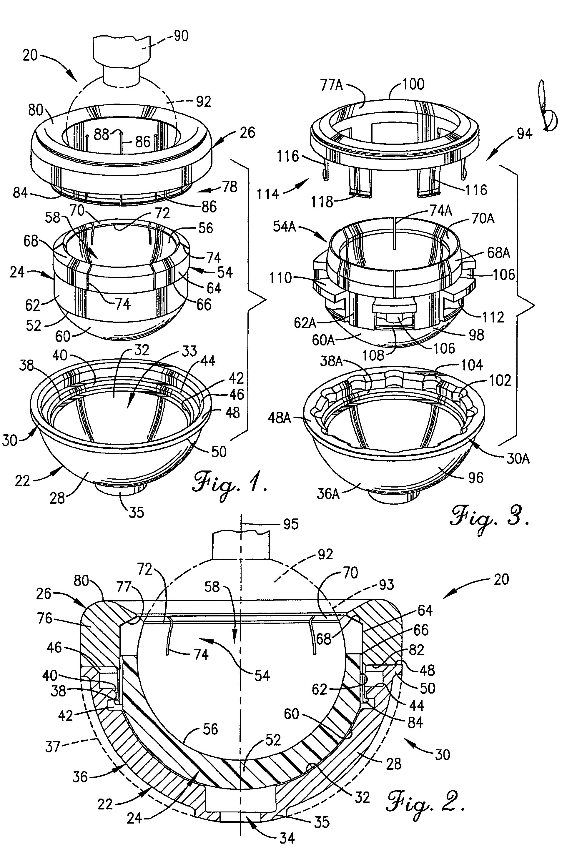
[0021]Turning now to the drawings, FIGS. 1 and 2 depict a hip prosthesis 20 having a shell 22, a liner 24, and a retainer ring 26. The hip prosthesis 20 shown forms an acetabular insert portion for total hip arthroplasty.

[0022]In greater detail, the substantially rigid, and preferably metal, shell 22 includes a shell wall 28 and a terminal shell margin 30. The shell wall 28 is generally cup-shaped and frustospherical having a substantially constant and spherical shell inner surface 32 defining a shell receiving area 33. An attachment opening 34 is formed in a shell base 36 of the shell wall 28. The attachment opening 34 extend through the shell wall 28 and a downwardly depending leg 35 which is integral to the shell wall. The shell wall also includes a porous coating 37. The shell wall 28 includes a circumferential catch ledge 38 having a circumferentially extending chamfer 40 on the upper corner thereof. An inwardly extending recessed region or lip receiving groove 42 extends circu...


PUM


Abstract

A hip prosthesis (20) having a shell (22), liner (24), and retainer ring (26) is utilized for hip arthroplasty. The liner (24) fits inside the shell (22), which is attached to a patient's pelvis, and the retainer ring (26) engages a terminal liner margin (54) to inhibit expansion of and decrease the size of a restricted liner opening (72) defined by the liner margin (54). By inhibiting expansion of the liner opening (72), the ball (92) of a patient's femur (90) is securely held in the liner (24). In one embodiment, the liner (98) is inhibited from rotation relative to the shell (96) by a plurality of protrusions (106) which mate with recesses (102) in the shell (96). In that embodiment, the liner (98) is provided with catch lips (108) to hold the liner (98) in the shell (96) and a positioning flange (110) which operates to form a relief gap (120) between the shell (96) and the liner (98). In another embodiment, the retainer ring comprises an attachment portion (128) and a retainer portion (130) with a threaded connection (132) between the attachment portion (128) and the retainer portion (130).

Description

BACKGROUND OF THE INVENTION[0001]1. Field of the Invention[0002]The present invention is broadly concerned with improved prostheses particularly designed for hip arthroplasties in order to securely hold the head of the femur, whether anatomical or prosthetic, thereby reducing the occurrences of dislocation of hip prostheses. More particularly, the invention pertains to a prosthesis for total hip arthroplasty comprising a metal ring constrained acetabular insert having a liner which is fixed to a person's pelvis by a shell to receive the prosthetic femur head in the liner. In preferred forms, the acetabular liner covers greater than 180° of the prosthetic femur head, and the metal ring is substantially rigid surrounding the opening of the liner to inhibit deformation of the liner and dislocation of the hip joint.[0003]2. Description of Prior Art[0004]To repair a hip joint, it is common to attach a shell to a patient's pelvis. A liner is typically received in the shell, and the ball o...

Claims


Application Information

Patent Timeline
Patent Type & Authority Patents(United States)
IPC IPC(8): A61F2/32
CPCA61F2/34A61F2/30767A61F2310/00011A61F2002/2825A61F2002/2828A61F2002/30331A61F2002/30354A61F2002/30367A61F2002/30403A61F2002/30405A61F2002/305A61F2002/30504A61F2002/30598A61F2002/3079A61F2002/30822A61F2002/30881A61F2002/3233A61F2002/3241A61F2002/3283A61F2002/3291A61F2002/3403A61F2002/3411A61F2002/347A61F2002/3493A61F2220/0025A61F2220/0033A61F2/32A61F2002/30495A61F2002/30594
Inventor MCQUEEN, DAVID A.ROTH, CHRISTOPH A.
Owner ORTHOPAEDIC RES INST
Why Eureka
Try Eureka