
Low threshold current switch

Active Publication Date: 2007-03-20
VERIS INDS
View PDF2 Cites 36 Cited by
  • Summary
  • Abstract
  • Description
  • Claims
  • Application Information

AI Technical Summary

Problems solved by technology

If the power cable current is too low, there may be insufficient energy to power the passive input circuit making current monitoring unreliable.
The current draw of many electrical devices, including fractional horsepower motors, is insufficient for reliable detection with this type of sensing circuitry.

Method used


Image

  • Low threshold current switch
  • Low threshold current switch
  • Low threshold current switch

Examples


Embodiment Construction

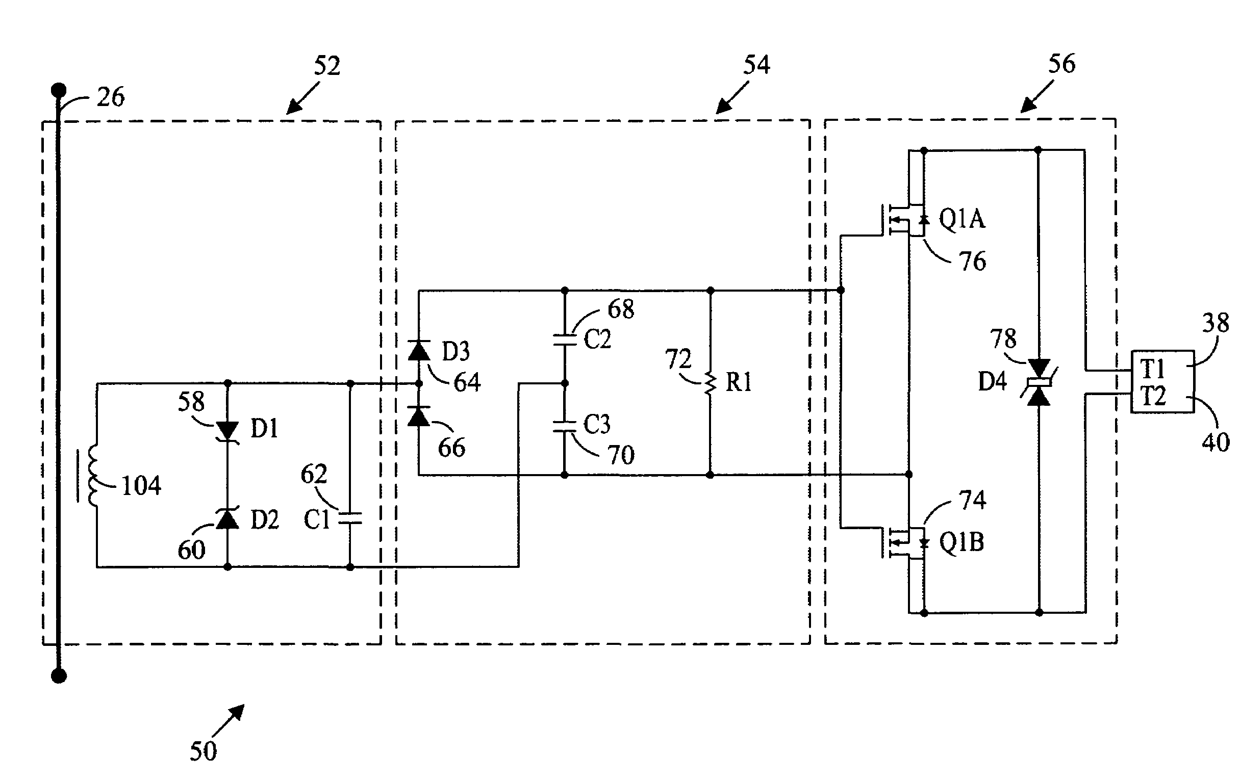
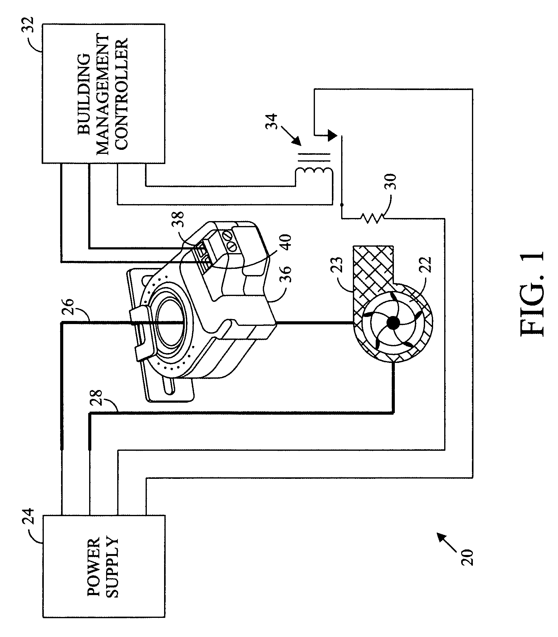
[0010]Referring in detail to the drawings where similar parts are identified by like reference numerals and referring more particularly to FIG. 1, an exemplary electrical system 20 includes an electrical load 22 that is connected to a power supply 24 by power cables 26, 28. By way of examples, loads may include valves, heaters, relays, lights, and motors that drive pumps, fans, etc. In the exemplary system, the load comprises a motor 22 that drives a fan 23 to force air over a heater 30 that is to operate only when the fan operating. The operation of the heater of the exemplary system is controlled by a relay 34 which, in turn, is controlled by a building management controller 32. A current switch 36 monitors the current flow in the power cable 26. When the fan motor 22 is running and current is flowing to the fan motor in the power cable 26, the current switch provides a first signal at the terminals 38, 40 which are conductively connected to the controller. When the current flow i...


PUM


Abstract

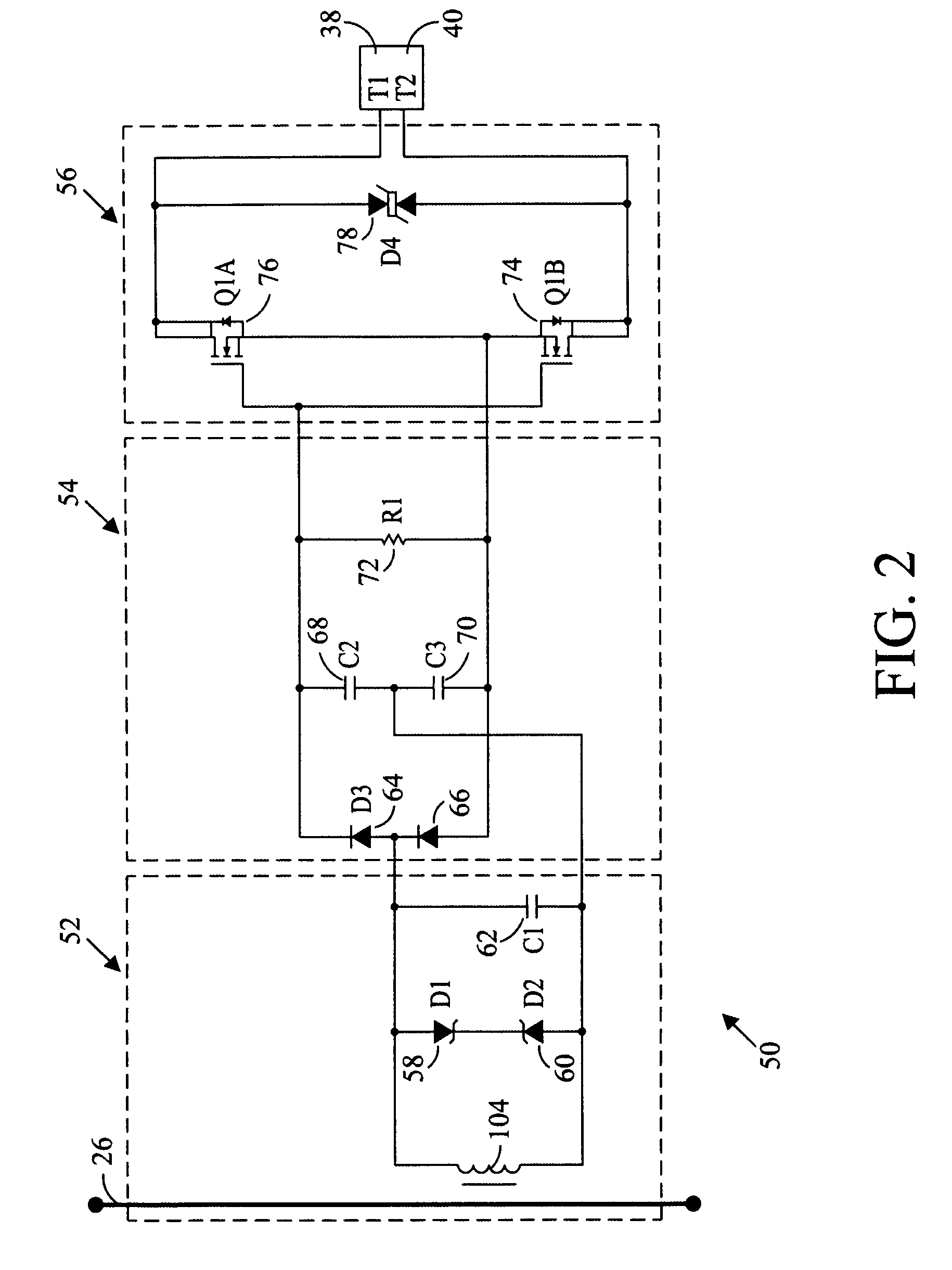
Low threshold current switch comprising a sensing transformer, a voltage multiplier and a switch enables monitoring a very low electric current in a power cable.

Description

CROSS-REFERENCE TO RELATED APPLICATIONS[0001]Not applicable.STATEMENT REGARDING FEDERALLY SPONSORED RESEARCH OR DEVELOPMENT[0002]Not applicable.BACKGROUND OF THE INVENTION[0003]The present invention relates to a current switch for monitoring low levels of electric current in a conductor.[0004]Electrical devices that draw very limited current, often only a small fraction of an amp, are used in large numbers in many industrial and residential environments. The operation of these devices, such as small fan motors and heaters, can be important to the protection of valuable property or successful completion of a process that may involve costly or hazardous equipment or materials. These devices may be stand-alone devices controlled by a local controller, but are often components of an automated system that are monitored and operated by a remotely located controller or building management computer. Typically, the operation of the device is tracked by a monitoring device, such as a current ...

Claims


Application Information

Patent Timeline
IPC IPC(8): G01R31/36G01R31/08G01R1/02
CPCG01R19/16547G01R15/18
Inventor BARON, MIKEBERNKLAU, JIM
Owner VERIS INDS
Learn More