Method and arrangement for controlling the position of an actuating element

Active Publication Date: 2007-03-20
ROBERT BOSCH GMBH
View PDF10 Cites 6 Cited by
  • Summary
  • Abstract
  • Description
  • Claims
  • Application Information

AI Technical Summary

Benefits of technology

[0005]Compared to the above, the method and arrangement of the invention for controlling the position of an actuating element afford the advantage that a check is made as to whether the distance between the desired value for the position of the actuating element and the at least one stop is less than a first pregiven value and, only in this case, is a change of the desired value limited. In this way, the desired value change limiting can be limited to the endangered range(s) wherein virtually no overshoots may occur or in which a specific displacement speed may not be exceeded when positioning the actuating element in order to prevent a movement against the at least one stop by the actuating elements and thereby prevent possible damage to the actuating element. It is true that overshoots can occur in the control of the actuating element but these overshoots do not take place in the above-mentioned endangered ranges and therefore do not lead to damage of the actuating element. By saving the desired value change limiting in non-endangered ranges in the above-described second method, a more rapid change of the desired value for the positioning of the actuating element is realized with a high dynamic and therefore the control of the position of the actuating element is accelerated.
[0006]Furthermore, with the desired value change limiting in the endangered regions, compared to the first-mentioned method, no offset between the at least one stop and the start of the displacement range is required or the offset can be minimized. This is especially advantageous for systems wherein a throughflow quantity is to be controlled by the position of an actuating element and wherein, for achieving a minimum throughflow quantity, the actuating element must be driven as close as possible to the at least one mechanical stop. This is, for example, an advantage for reducing the lea

Problems solved by technology

Furthermore, with the desired value change limiting in the endangered regions, compared to the first-mentioned method, no

Method used


Image

  • Method and arrangement for controlling the position of an actuating element
  • Method and arrangement for controlling the position of an actuating element
  • Method and arrangement for controlling the position of an actuating element

Examples


Example

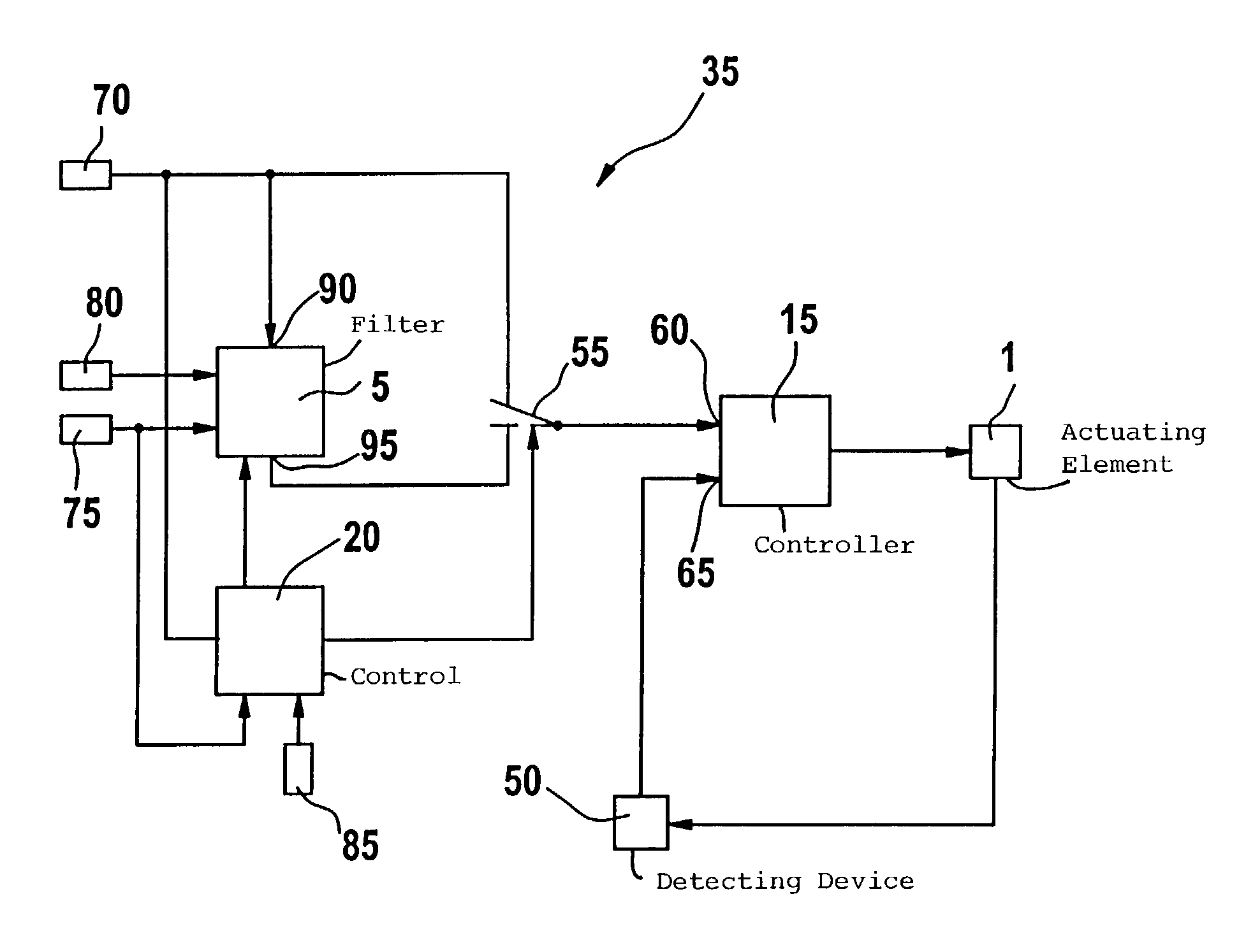
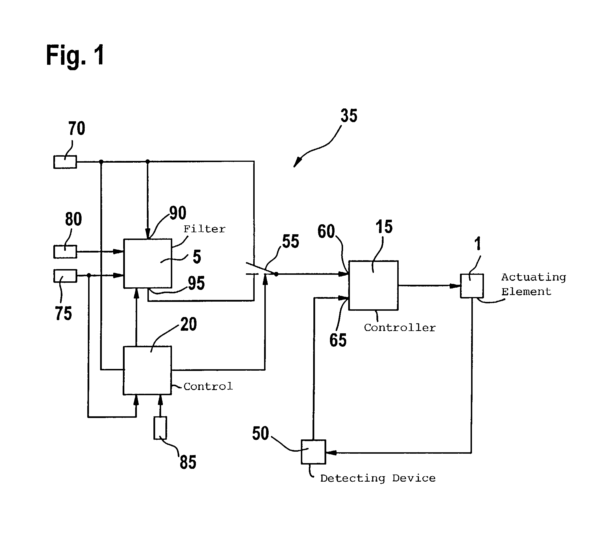
[0016]In FIG. 1, reference numeral 35 identifies an arrangement for controlling the position of an actuating element 1. Means 15 are provided for bringing the position of the actuating element closer to a desired value within a displacement range. The means 15 can, for example, be configured as a controller which causes an actual value for the position of the actuating element 1 to track the desired value within the displacement range of the actuating element 1. At least one stop for the actuating element 1 is provided which limits the displacement range of the actuating element. The actuating element 1 can be maximally driven up to the at least one stop. A displacement of the actuating element beyond the at least one stop is not possible. The at least one stop can, for example, be a mechanical stop.

[0017]In FIG. 4, an example of such an actuating element 1 is shown. The actuating element 1 can, for example, be a throttle flap, a charge movement flap, an exhaust-gas recirculation va...


PUM


Abstract

The invention is directed to a method and an arrangement for controlling the position of an actuating element (1) which prevent damage to the actuating element by a collision with at least one stop (25, 30) and simultaneously ensure good dynamic characteristics. The position of the actuating element (1) tracks a desired value within a displacement range. The displacement range is limited for the actuating element (1) by at least one stop (25, 30). A check is made as to whether the distance between the desired value for the position of the actuating element (1) and the at least one stop (25, 30) drops below a pregiven value (S1). Only in this case is a change of the desired value limited.

Description

BACKGROUND OF THE INVENTION [0001]Methods are already known for controlling the position of an actuating element configured as a throttle flap, an exhaust-gas recirculation valve or as a charge movement flap. The position of the actuating element within a displacement range tracks a desired value and the displacement range is limited by at least one stop for the actuating element.[0002]For the position of the actuating element, a digital control is utilized in a motor vehicle which is carried out by the engine control apparatus. For example, the two methods discussed below are used.[0003]In a first method, a sufficiently high scanning rate must be ensured for the control of the position of the actuating element. Here, it must be prevented that the mechanical stops are not driven against in order to avoid damage to the actuating elements. For this purpose, the displacement range is limited with the aid of an offset. For the described systems having high scanning rates, the offset can...

Claims


Application Information

Patent Timeline
IPC IPC(8): G05B13/02F02D31/00G06F7/00F02D9/02G05B19/4061
CPCG05B19/4061G05B2219/49144G05B2219/49137
Inventor GROSSMANN, ALEXBAUMANN, TORSTEN
Owner ROBERT BOSCH GMBH
Why Eureka
Try Eureka