Method for use in making a write coil of magnetic head

a write coil and write head technology, applied in the field of magnetic heads, can solve the problems of increasing the thickness of the write coil, increasing the thickness of the plating, and difficulty in etching the seed materials from the top of the structure in this manner

Inactive Publication Date: 2007-03-27
WESTERN DIGITAL TECH INC
View PDF10 Cites 62 Cited by
  • Summary
  • Abstract
  • Description
  • Claims
  • Application Information

AI Technical Summary

Problems solved by technology

For high aspect ratio structures, a problem arises when seed layer 1004 between each coil layer 1002 needs to be removed after the electroplating step.
Note that it is difficult to etch the seed materials from the top of the structure in this manner, as the coil layers are relatively tall and the pitch between coil layers is narrow.
The drawback to this approach is the increased depletion of the write coil thickness, which requires increasing the plating thickness of the write coils.
Namely, since the ejected species in both approaches are not inherently volatile, redeposition can occur and cause an electrical shorting of the write coils.
Thus, since both techniques use purely physical processes to remove the seed materials, their selectivity is generally poor and over-etching tends to cause damage to the top coil structure and change the topography to the extent that it introduces more complications during subsequent fabrication steps.
When the write coil's aspect ratio increases (i.e. the pitch between coil layers is reduced), however, the damascene technique has its limitations.
For example, fabrication issues become more apparent when the pitch between coil layers is 0.5 microns or less.
For one, the seed layer deposition becomes non-uniform.
In addition, the damascene filling within the trenches is also non-uniform and voids (e.g. a void 1504 in FIGS. 14–15) remain within the structure after the electroplating.
Furthermore, the damascene technique for such high aspect ratio structures is limited to metals which do not produce hydrogen evolution during electroplating; thus the technique is not applicable to magnetic materials which are used to form other structures within a magnetic head.

Method used


Image

  • Method for use in making a write coil of magnetic head
  • Method for use in making a write coil of magnetic head
  • Method for use in making a write coil of magnetic head

Examples


Embodiment Construction

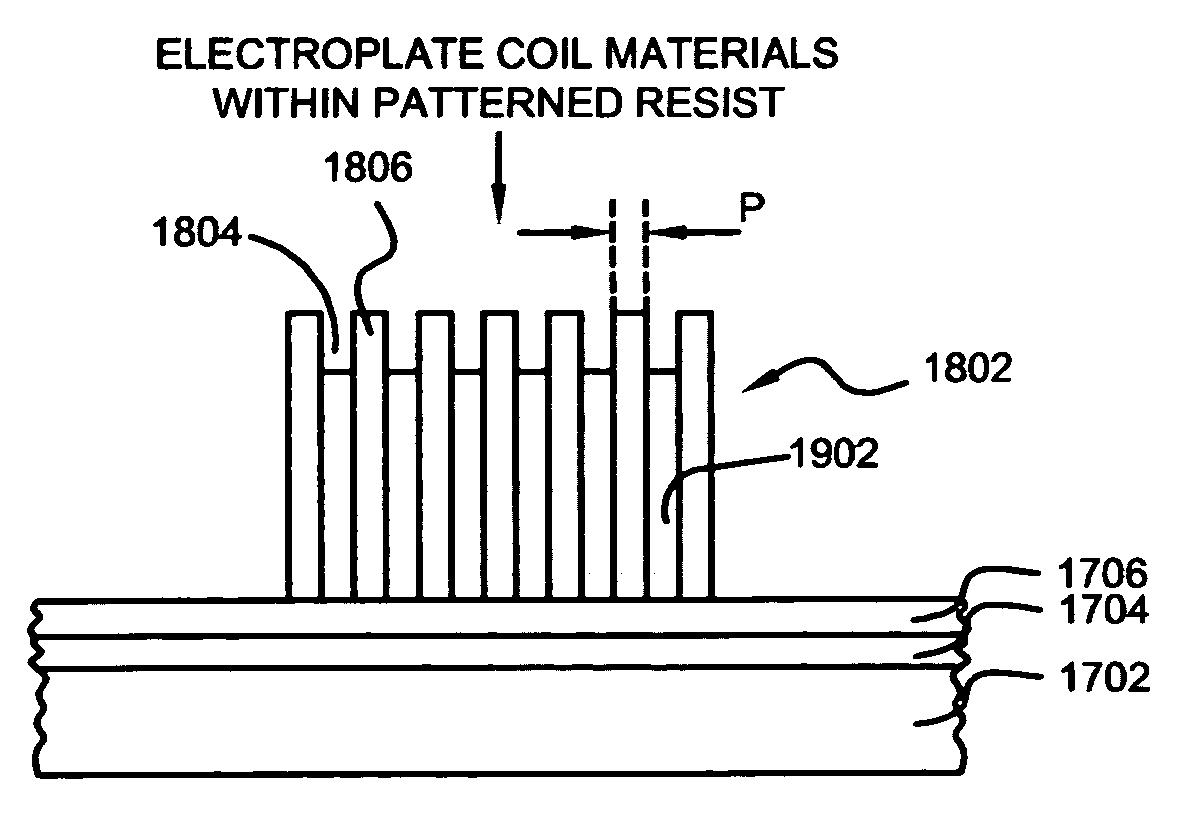
[0026]The methods described herein are suitable for fabricating a write coil of a magnetic head where a pitch between coil layers is 0.5 microns or less. The method includes the steps of forming a seed layer made of ruthenium (Ru) over a substrate; forming, over the seed layer, a patterned resist having a plurality of write coil trenches patterned therein; electroplating electrically conductive materials within the plurality of write coil trenches to thereby form a plurality of write coil layers; removing the patterned resist; and performing a reactive ion etch (RIE) in ozone gas for removing exposed seed plurality materials in between the plurality of write coil layers. Advantageously, the plurality of write coil layers remain unetched from the RIE in ozone gas. Other structures may be fabricated in a similar manner.

[0027]The following description is the best embodiment presently contemplated for carrying out the present invention. This description is made for the purpose of illust...


PUM

PropertyMeasurementUnit
distanceaaaaaaaaaa
thicknessaaaaaaaaaa
thicknessaaaaaaaaaa

Abstract

Methods suitable for use in making a write coil of a magnetic head includes the steps of forming a seed layer made of ruthenium (Ru) over a substrate; forming, over the seed layer, a patterned resist having a plurality of write coil trenches patterned therein; electroplating electrically conductive materials within the plurality of write coil trenches to thereby form a plurality of write coil layers; removing the patterned resist; and performing a reactive ion etch (RIE) in ozone gas (O3) for removing exposed seed layer materials in between the plurality of write coil layers. Advantageously, the write coil layers remain undamaged from the RIE in the ozone gas. Other structures may be fabricated in a similar manner.

Description

BACKGROUND OF THE INVENTION[0001]1. Field of the Invention[0002]This invention relates generally to magnetic heads in disk drives, and more particularly to improved methods of making write coils of magnetic write heads as well as other structures with use of a ruthenium (Ru) seed layer for electroplating and a reactive ion etch (RIE) in ozone gas for seed removal.[0003]2. Description of the Related Art[0004]A write head is typically combined with a magnetoresistive (MR) read head to form a merged MR head, certain elements of which are exposed at an air bearing surface (ABS). The write head comprises first and second pole pieces connected at a back gap that is recessed from the ABS. The first and second pole pieces have first and second pole tips, respectively, which terminate at the ABS. An insulation stack, which comprises a plurality of insulation layers, is sandwiched between the first and second pole pieces, and a coil layer is embedded in the insulation stack. A processing circ...

Claims


Application Information

Patent Timeline
Patent Type & Authority Patents(United States)
IPC IPC(8): G11B5/127B44C1/22C25D5/02
CPCG11B5/1272G11B5/17G11B5/3163Y10T29/49064Y10T29/49062Y10T29/49052Y10T29/49048Y10T29/49032Y10T29/4906
Inventor BONHOTE, CHRISTIAN RENELE, QUANG
Owner WESTERN DIGITAL TECH INC
Why Eureka
Try Eureka