Fuel injection system of internal combustion engine

a fuel injection system and internal combustion engine technology, applied in the direction of fuel injecting pumps, machines/engines, electric control, etc., can solve the problems of vehicle operability deterioration, emission invite, etc., and achieve good engine operability and good emission

Inactive Publication Date: 2007-03-27
TOYOTA JIDOSHA KK
View PDF23 Cites 18 Cited by
  • Summary
  • Abstract
  • Description
  • Claims
  • Application Information

AI Technical Summary

Benefits of technology

[0004]An object of the present invention is to provide a fuel injection system of an internal combustion engine able to secure good emission and good engine operability.

Problems solved by technology

If the fuel properties change, the problems arise that deterioration of emission is invited or vehicle operability deteriorates.

Method used


Image

  • Fuel injection system of internal combustion engine
  • Fuel injection system of internal combustion engine
  • Fuel injection system of internal combustion engine

Examples


Embodiment Construction

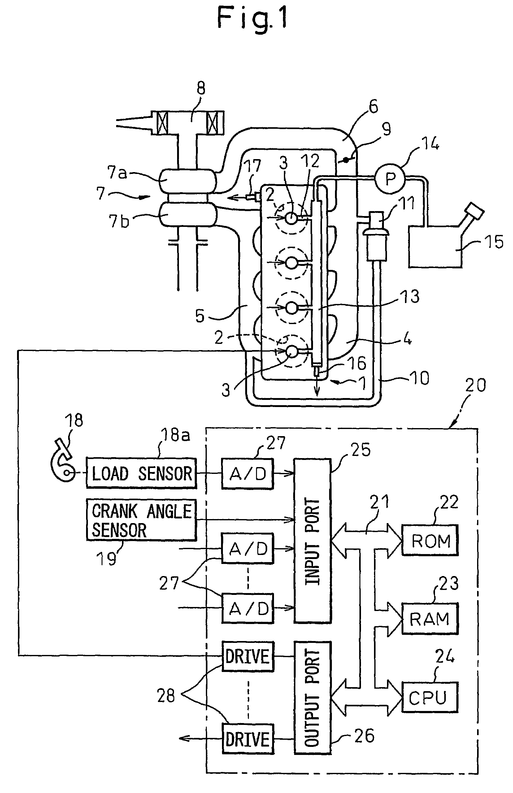
[0019]Referring to FIG. 1, 1 is a compression ignition type internal combustion engine body, 2 a combustion chamber of a cylinder, 3 a fuel injector for injecting fuel into a combustion chamber 2, 4 an intake manifold, and 5 an exhaust manifold. The intake manifold 4 is connected through an intake duct 6 to an outlet of a compressor 7a of an exhaust turbocharger 7. The inlet of the compressor 7a is connected to an air cleaner 8. The intake duct 6 has arranged inside it a throttle valve 9 driven by a step motor. On the other hand, the exhaust manifold 5 is connected to an inlet of an exhaust turbine 7b of the exhaust turbocharger 7.

[0020]The exhaust manifold 5 and the intake manifold 4 are connected to each other through an exhaust gas recirculation (hereinafter referred to as an “EGR”) passage 10. The EGR passage 10 has an electronic control type EGR control valve 11 arranged in it. On the other hand, each fuel injector 3 is connected through a fuel feed line 12 to a common rail 13....


PUM


Abstract

An internal combustion engine provided with a common rail (13) and fuel injectors (3) connected to the common rail (13). When pilot injection is performed, the injection pressure pulsates. At this time, the injection amount of the main injection fluctuates by a certain fluctuation pattern. If indicating on an abscissa a time interval from when pilot injection is started to when main injection is started and indicating on the ordinate a fluctuation amount of main injection, the fluctuation pattern of the injection amount of the main injection becomes a form contracted or expanded in the abscissa direction in accordance with the fuel properties. This characteristic is utilized to find the fluctuation amount of the injection amount of the main injection.

Description

TECHNICAL FIELD[0001]The present invention relates to a fuel injection system of an internal combustion engine.BACKGROUND ART[0002]An internal combustion engine designed so that the fuel injectors are connected to a common rail through high pressure lines and performing a plurality of fuel injections in a single cycle, for example two pilot injections and a succeeding main injection, is known (for example, see Japanese Unexamined Patent Publication (Kokai) No. 2000-18074). In this internal combustion engine, the main fuel injection is calculated from a map, and the injection amounts and injection timings of the first and second pilot injections are calculated from maps based on the main injection amount and the engine speed.[0003]In such an internal combustion engine, however, if the fuel used changes, the fuel properties change. If the fuel properties change, the problems arise that deterioration of emission is invited or vehicle operability deteriorates.DISCLOSURE OF INVENTION[000...

Claims


Application Information

Patent Timeline
Patent Type & Authority Patents(United States)
IPC IPC(8): F02M59/46F02B3/00F02D41/04F02D41/08F02D41/38F02D41/40
CPCF02D41/3809F02D41/401F02D41/402F02D41/403F02D41/08Y02T10/44F02D41/405F02D2200/0604F02D2200/0612F02D2250/04Y02T10/40
Inventor TSUTSUI, TSUNEO
Owner TOYOTA JIDOSHA KK
Why Eureka
Try Eureka