Roll up ramp system

a technology of rolling ramps and ramps, which is applied in the direction of roofs, bridges, transportation items, etc., can solve the problems of heavy weight of foldable or collapsible ramp structures, difficult and tiresome loading of machinery of this kind, into a hauling vessel such as a truck or a wagon, and achieve the effect of maximizing loading capacity and minimizing slippag

Inactive Publication Date: 2007-03-27
AULICINO KENNETH M
View PDF24 Cites 11 Cited by
  • Summary
  • Abstract
  • Description
  • Claims
  • Application Information

AI Technical Summary

Benefits of technology

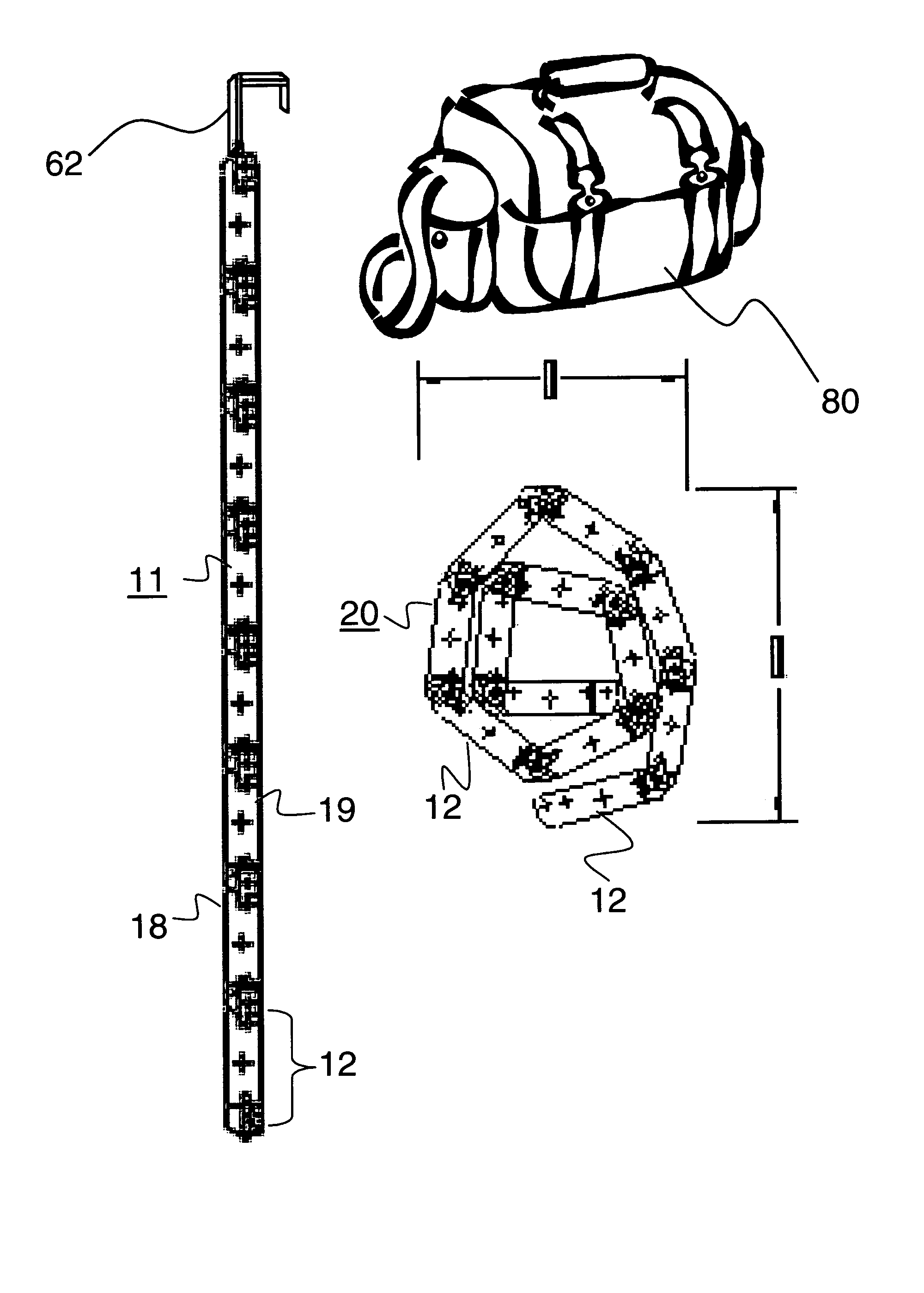
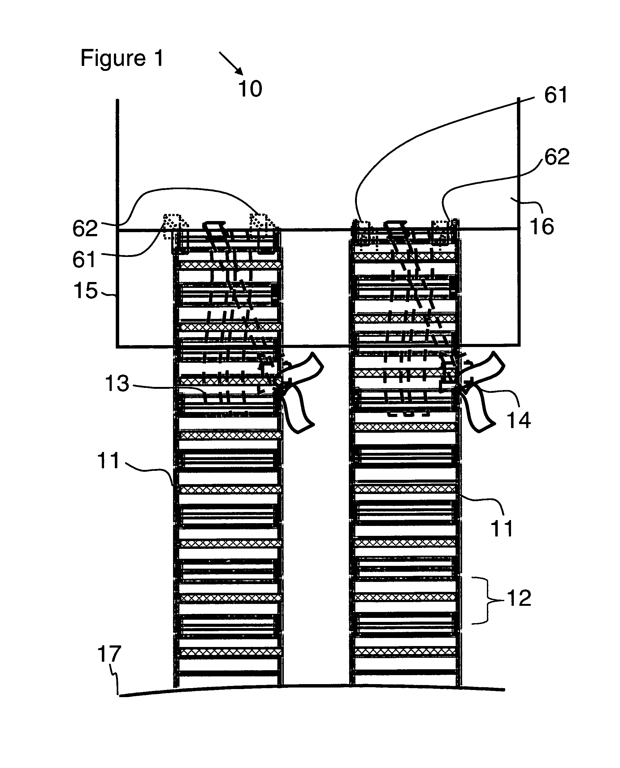
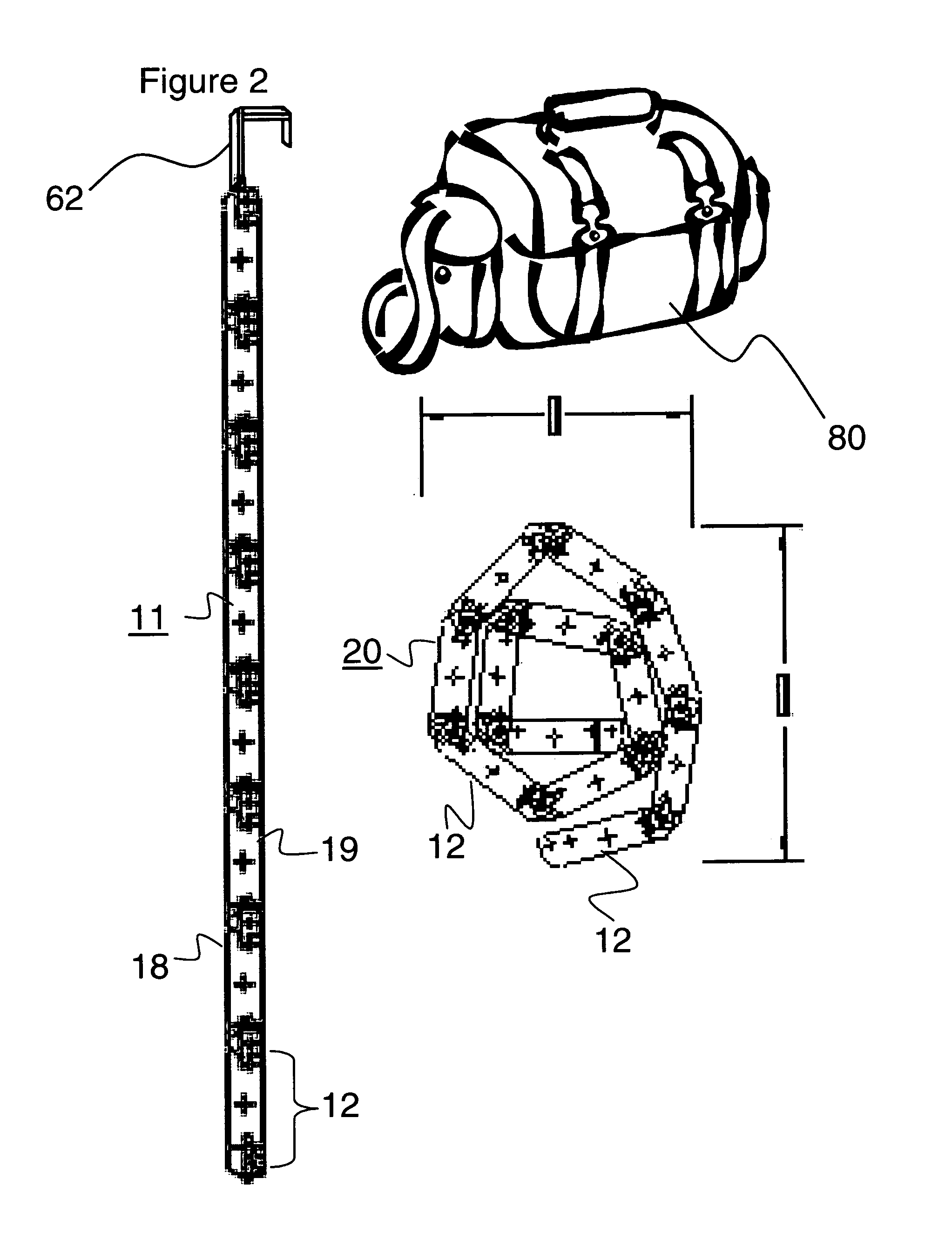
[0018]The roll up ramp system is composed of a lightweight metal or plastic material. This lightweight structure enhances the convenience factor of the roll up ramp system. As a result, the lightweight, durable, ramp structure can be readily rolled up for storage and easily deployed from a rolled up condition to a ramp configuration. It can be readily adapted for use as temporary ramping for wheelchair access to non compliant buildings. For example, the roll up ramp system can be placed on stairs to accommodate wheelchairs as a temporary fix.
[0021]Each of the plurality of links comprising the roll up ramp system has a length ranging from ¼–1 feet. Preferably, each of the links comprising the roll up ramp system has a length ranging from ½–¾ feet. The central support rods, lateral locking rods, and linking support rods may be coated with a non-skid surface material. Alternatively, the central support rods, lateral locking rods, and linking support rods may have treaded grooves thereon. The non-skid surface material and treaded grooves serve to cause friction between the roll up ramp system and an object, such as a lawnmower, snow blower or the like, traversing the system, thereby providing optimum loading capability and minimizing slippage.

Problems solved by technology

Loading machinery of this kind, which is generally heavy and cumbersome in nature, into a hauling vessel, such as a truck or wagon, is often times difficult and tiresome.
Foldable or collapsible ramp structures heretofore disclosed and utilized are bulky by nature and design.
These ramp structures have common disadvantages.
They are generally cumbersome to arrange in both the ramp and folded configurations, and they are heavy.
Still other designs utilizing chain-linking configurations that lock to form bridges or ladders provide inadequate support.
They are inconvenient to use, and are frequently incapable of supporting heavy loads.
Furthermore, the ramp structures heretofore disclosed and utilized do not enable convenient secure attachment to the hauling vessel.
Many of the foldable or collapsible ramp structures heretofore disclosed and utilized have a tendency to be bulky and heavy due to the panel arrangement utilized when forming the ramp.
None of these references disclose a ramp configuration comprising a plurality of links formed of a lightweight rod construction that enables the ramp to be lightweight and easily rolled for storage.
Like the paneled arrangement ramps, these ramps have a tendency to be bulky and heavy due to the nature of the links utilized in the configuration.
Chain linking configurations that link and lock to form ladders, bridges, or chains have heretofore been disclosed and utilized, however, theses apparatuses do not provide support and ready convenience, and may not be capable of supporting heavy loads.
Significantly, none of the foldable ramps or chain, ladder, or bridge structures provides a roll up configuration that is capable of supporting heavy loads when placed in the straight or ramp formation, and which is additionally capable of being rolled up for storage.
None of the ramps disclosed or utilized provides a ramp structure that is capable of handling heavy loads associated with equipment, including lawn mowers, JET SKI™s (personal watercrafts (PWCs)), snowmobiles, ATV s and the like.

Method used


Image

  • Roll up ramp system
  • Roll up ramp system
  • Roll up ramp system

Examples


Embodiment Construction

[0027]The present invention provides a roll up ramp system for facilitating transition between a first elevation and a second, higher elevation, such as a tailgate portion of a land vehicle, the landing associated with a flight of stairs, a loading dock, or the like. Generally stated, the roll up ramp system comprises a securement device, a plurality of links, a plurality of selvedge linking units, and a plurality of linking support rods. These elements are arranged to form a roll up ramp adapted to form a ramp configuration and a roll up configuration as force is applied. The ramp configuration of the roll up ramp system is achieved when force is applied to the top surface of each of the links. The roll up configuration of the roll up ramp system is achieved when force is applied to the bottom surfaces of the links.

[0028]Chain link rigidity is provided when the links are flexed in one direction but not for the opposing direction, whereupon a flexible connection is achieved. As a re...


PUM


Abstract

A roll up ramp system facilitates transition between a first elevation and a second, higher elevation. The roll up ramp system includes a securement device temporarily connecting a roll up ramp to the second, higher elevation. Further included by the roll up ramp system are a plurality of links formed by a set of parallel plates interconnected by a central support rod and a pair of lateral locking rods. Each of the locking rods is provided with a plurality of selvedge linking units having a locking portion and a pivot portion. The links are interconnected by a plurality of linking support rods, which are accommodated by each of the selvedge linking units to form a roll up ramp. A rigid, durable ramp configuration is thereby achieved. The roll up ramp system is lightweight, strong, conveniently stored in a rolled up condition and readily deployed in an unrolled, ramp-like configuration to facilitate loading and unloading of equipment from a hauling vehicle.

Description

BACKGROUND OF THE INVENTION[0001]1. Field of the Invention[0002]The invention relates to a roll up ramp system for loading and unloading machinery from a hauling vehicle; and more particularly, to a ramp system that can be rolled up for storage and unrolled to form a durable, rigid ramp capable of releasable attachment to the hauling vehicle.[0003]2. Description of the Prior Art[0004]Today's active society calls for the hauling and transporting of a variety of equipment and machinery, such as lawn mowers, snow blowers, snow mobiles, JET SKI™s (personal watercrafts (PWCs)), ATVs and the like. Loading machinery of this kind, which is generally heavy and cumbersome in nature, into a hauling vessel, such as a truck or wagon, is often times difficult and tiresome. To avoid actually lifting the machinery, which might require several persons, ramp structures are widely utilized. Foldable or collapsible ramp structures provide an especially convenient means for loading machinery into the ha...

Claims


Application Information

Patent Timeline
Patent Type & Authority Patents(United States)
IPC IPC(8): E01D19/04B60P1/43B65G69/30
CPCB60P1/43
Inventor AULICINO, KENNETH M.
Owner AULICINO KENNETH M
Why Eureka
Try Eureka