Droplet ejection apparatus and its drive method

a technology of droplet ejection and drive method, which is applied in the direction of printing, other printing apparatus, etc., can solve the problems of increasing the viscosity of the ink whose viscosity is increased, the ejection is very difficult, and the ejection is difficult to stably eject the ink from the recording head, so as to reduce the initial flying speed and increase the viscosity of the liquid

Active Publication Date: 2007-03-27
KONICA MINOLTA INC
View PDF15 Cites 21 Cited by
  • Summary
  • Abstract
  • Description
  • Claims
  • Application Information

AI Technical Summary

Benefits of technology

[0016]Herein, the decapping characteristic indicates a lowered amount of the initial flying speed by the so-called decapping phenomenon that, in the situation in which the nozzle surface is opened, the viscosity of the liquid is increased by the meniscus drying.

Problems solved by technology

Such a high viscosity ink is, as far as it is ejected under the normal temperature and normal humidity, when the drive voltage of the recording head is a little increased, it can be ejected, but because the viscosity is increased under the low temperature circumstance and is not smaller than 10 cp, and further, because the volatilization of the ink composition from the surface of the meniscus is fast under the low humidity circumstance, the ink viscosity of the nozzle surface is rapidly increased, and the ejection becomes very difficult.
As described above, it is very difficult to eject stably the ink whose viscosity is increased from the recording head under the low temperature circumstance and low humidity circumstance.
Further, in order to conduct the stable ejection, it is necessary that the ink droplet is ejected after the vibration of the meniscus by the micro-vibration is turned down and under the condition that the meniscus position is settled at predetermined position, and when the ink droplet is ejected in a situation other than this, a size of the ejected ink droplet or the flying speed is varied, resulting in a cause of landing position error.
Further, in order to effectively stir and mix the ink, it is necessary that the meniscus is largely vibrated, however, when the high frequency drive is conducted, the vibration of the meniscus needs to be attenuated early.
However, because the residual pressure is not cancelled, and the vibration of the meniscus remains, the ink droplet cannot be ejected at once.
Therefore, after the micro-vibration is given to the meniscus, because there is a time before the ink is ejected, the ink viscosity is increased again in that time, and particularly, under the low temperature and low humidity circumstance, there is a problem that the normal ejection becomes difficult.
Further, in the trapezoidal wave, the circuit structure becomes complicated, and further, because the voltage sensibility becomes low, the necessary drive voltage is increased and the power consumption is increased.
Further, when a number of times of applying of the micro-vibration pulse is not increased, the sufficient effect can not be obtained, and as a result, there is a problem that it results in a decrease of the printing speed.

Method used


Image

  • Droplet ejection apparatus and its drive method
  • Droplet ejection apparatus and its drive method
  • Droplet ejection apparatus and its drive method

Examples


example

(The Evaluation 1 of the Ejection Stability)

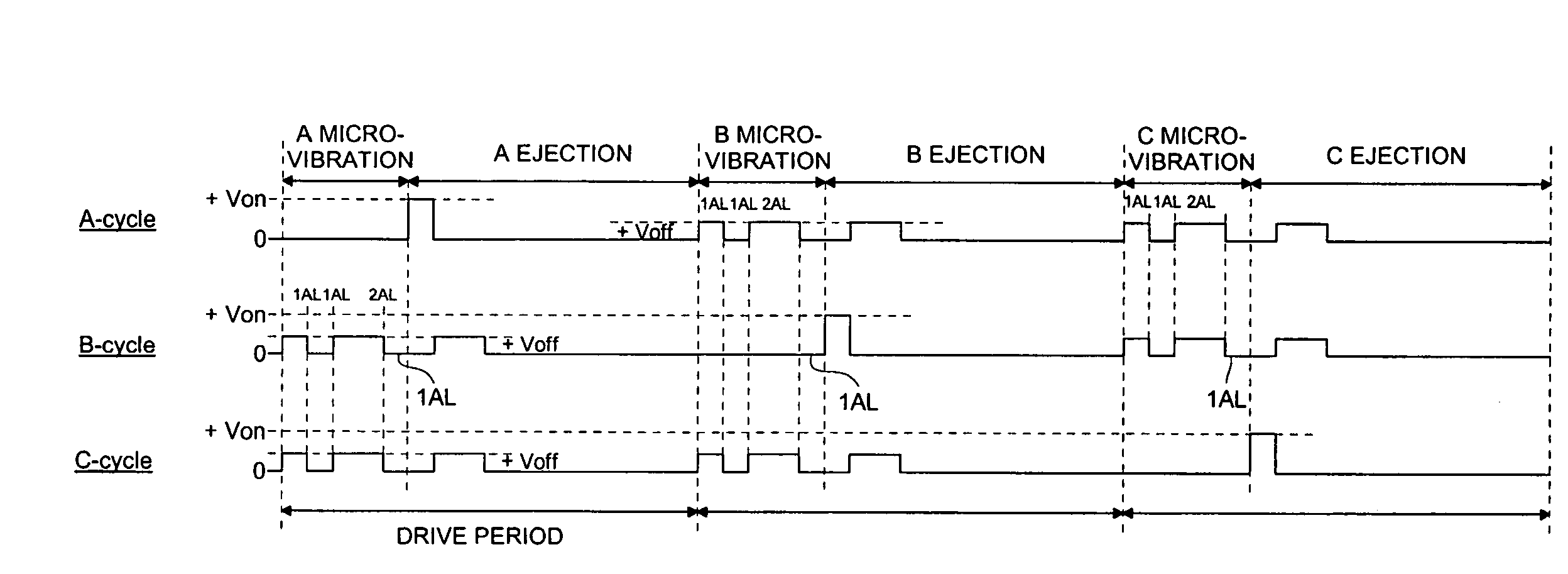
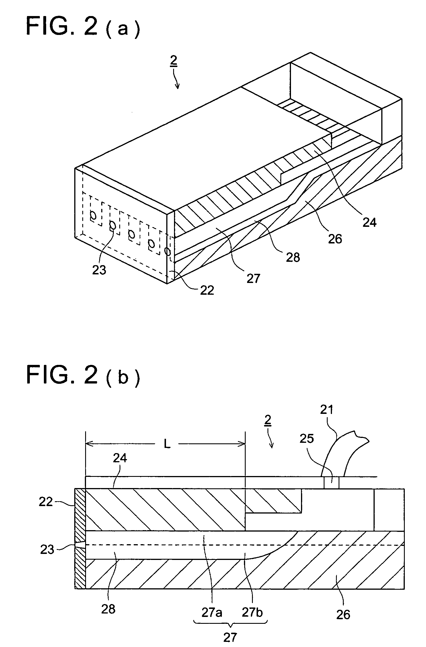
[0114]Each channel of the recording head (number of nozzles: 256, nozzle diameter is 23 μm) of the shear mode type shown in FIG. 2, is divided into 3 groups as shown in FIG. 4, and by using the micro-vibration pulse and ejection pulse shown in FIGS. 10(a)–(f), 3 cycle drive is conducted under the following condition. The result in which the ejection stability at this time is measured by the following method, is shown in Table 1.

Condition

[0115]Head: AL=2.0 μs[0116]Ink: aqueous ink, (viscosity: 5.5 mPa·s, surface tension: 41 mN / m at 25° C.)[0117]Drive voltage ratio: Von / Voff=2 / 1[0118]Drive period: 33 μs

[0119]Measuring Method of the Ejection Stability

[0120]In respective micro-vibration pulse applying conditions, by changing the voltage Von, Voff, the flying speed of the ink droplet is increased, and the flying situation of the ink droplet is observed. The upper limit of the flying speed in which the curving of the ejection direction and the s...


PUM


Abstract

A droplet ejection apparatus provided with: a drive signal generator for generating drive signals including a plurality of drive pulses; a drive pulse selector for selecting drive pulses in accordance with a print datum of each pixel; and a head for ejecting a droplet from a nozzle provided corresponding to a channel, by changing a volume of the channel according to the drive pulses selected, wherein, the drive signal includes a micro-vibration pulse as one of the drive pulses to generate a micro-vibration of meniscus in the nozzle in such a degree that the droplet is not ejected, said micro-vibration pulse being formed of rectangular waves which include at least one micro-vibration pulse having a pulse width of (2n) AL, where AL is ½ of the acoustic resonance period of the channel, and n is an integer not smaller than 1.

Description

BACKGROUND OF THE INVENTION[0001]The present invention relates to a droplet ejection apparatus and its drive method, and in more detail, to a droplet ejection apparatus and its drive method in which, by applying a micro-vibration to a liquid meniscus in a nozzle in a degree in which the droplet is made not to be ejected, an increase of viscosity of the liquid in the nozzle is suppressed.[0002]As a droplet ejection head in which the droplet is ejected from the nozzle when a volume of a channel is made changed, an ink jet recording head to record an inkjet image is well known.[0003]The viscosity of the ink for the inkjet used for this inkjet recording head is, normally, about 2–5 cp (centipoise) in a room temperature. However, recently, accompanied with an offering of the high performance, additives are increased, and the ink with the high viscosity of 5–10 cp in the room temperature is also increased. Such a high viscosity ink is, as far as it is ejected under the normal temperature ...

Claims


Application Information

Patent Timeline
Patent Type & Authority Patents(United States)
IPC IPC(8): B41J29/38B41J2/045B41J2/14
CPCB41J2/04581B41J2/04588B41J2/14209B41J2/04596B41J2/04593
Inventor KITAMI, AKIKOASANO, KAZUO
Owner KONICA MINOLTA INC
Why Eureka
Try Eureka