Vehicle mirror with secondary lighting lens for ground illuminator

a secondary lens and vehicle mirror technology, applied in fixed installations, lighting and heating devices, lighting support devices, etc., can solve the problems of burning people, the cost of light emitting diodes that would be required to provide illumination equivalent to that provided by incandescent bulbs is much higher than incandescent bulbs, and achieves the effect of reducing thermal conductivity and minimizing the temperature of primary lenses

Inactive Publication Date: 2007-03-27
MAGNA MIRRORS OF AMERICA INC
View PDF51 Cites 13 Cited by
  • Summary
  • Abstract
  • Description
  • Claims
  • Application Information

AI Technical Summary

Benefits of technology

[0007]A ground illuminator for an external vehicle rearview mirror comprises an electrical light bulb installed in a housing having a transparent primary lens. A secondary lens is interposed between the housing and the primary lens, and is spaced from the primary lens. The spacing between the lenses reduces the thermal conductivity between the lenses and provides a channel for airflow between the lenses, thereby minimizing the temperature of the primary lens due to illumination of the light bulb.

Problems solved by technology

In a large vehicle application, the temperature of the ground illuminator lens can exceed 115° C. Because the ground illuminator lens is typically coextensive with the mirror housing and is therefore accessible, contact with the lens is likely and, at high temperatures, can result in a person suffering burns.
However, the light emitting diodes that would be required to provide illumination equivalent to that provided by an incandescent bulb are far more costly than an incandescent bulb.

Method used


Image

  • Vehicle mirror with secondary lighting lens for ground illuminator
  • Vehicle mirror with secondary lighting lens for ground illuminator
  • Vehicle mirror with secondary lighting lens for ground illuminator

Examples


first embodiment

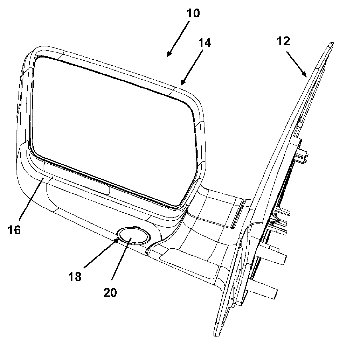
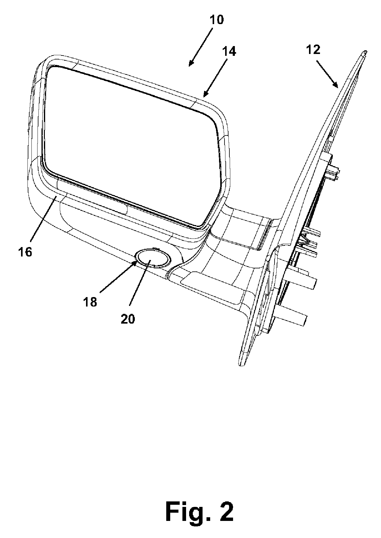
[0024]Referring now to FIGS. 3–5, the ground illuminator 18 comprises a housing 22 enclosing an incandescent light bulb 24, a reflector 26, and a pair of power terminals providing power to and supporting the light bulb 24. The housing 22 is mounted in a suitable manner, such as with fasteners, interference fittings, friction fittings, and the like, to the mirror housing 16 at a lower portion thereof for directing light from the light bulb 24 to an area exterior of the rearview mirror assembly 10. A lens stack comprises a primary lens 20 and a secondary lens 40. The primary lens 20 protects the light bulb against impact, debris, and weather, and can be adapted to modulate the light provided by the light bulb 24, such as with a convex configuration 60, as illustrated in FIGS. 6 and 7, for magnifying the illumination. In the embodiment illustrated in FIG. 5, the primary lens 20 comprises a fresnel lens to direct the light in a particular region.

[0025]The ground illuminator 18 is provid...

second embodiment

[0032]Referring again to FIGS. 6 and 7, a second embodiment comprising an alternate configuration of the lens stack is illustrated. In this embodiment, the secondary lens 40 is eliminated, and the primary lens 20 is mounted in the housing 22 adjacent the light bulb 24, thus serving as a secondary lens. An alternate primary lens 60 comprises a somewhat flattened, circular body having a ring flange 62 extending orthogonally away from the plane of the lens 60 along and adjacent the circumference of the lens 60. The ring flange 62 encloses a center convex portion 64 which is convex away from the light bulb 24 when assembled to the housing 22, thereby defining a space between the convex portion 64 and the lens 20. The ring flange 62 is interrupted by a gap 66.

[0033]The lens 20 is illustrated in FIG. 7 as a fresnel lens. The lens 20 is mounted in the housing 22 in a suitable, generally well-known manner, such as sonic welding or an adhesive, and the lens 60 is attached over and to the len...


PUM


Abstract

A ground illuminator for an external vehicle rearview mirror comprises an electrical light bulb installed in a housing having a transparent primary lens. A secondary lens it is interposed between the housing and the primary lens, and is spaced from the primary lens. The spacing between the lenses reduces the thermal conductivity between the lenses and provides a channel for airflow between the lenses, thereby minimizing the temperature of the primary lens due to illumination of the light bulb.

Description

CROSS-REFERENCE TO RELATED APPLICATION[0001]This application claims the benefit of U.S. provisional application Ser. No. 60 / 521,762, filed Jun. 30, 2004, which is incorporated herein in its entirety.FIELD OF THE INVENTION[0002]The invention relates generally to area lights for vehicle rearview mirrors, and more particularly to a secondary lens for an area light for reducing the temperature of a primary lens caused by the illumination of a light bulb.DESCRIPTION OF THE RELATED ART[0003]External rearview mirrors are ubiquitous for motor vehicles. Conventional external rearview mirrors are increasingly incorporating additional functionality, such as area lights, also known as ground illuminators or pot lights. U.S. Pat. Nos. 5,371,659, 5,823,654, 6,074,077, and 6,149,287 disclose rearview mirrors incorporating area lights for illuminating the area adjacent a vehicle.[0004]The ground illuminator is typically utilized on rearview mirrors as a safety feature, and comprises an incandescent...

Claims


Application Information

Patent Timeline
Patent Type & Authority Patents(United States)
IPC IPC(8): B60Q1/26
CPCB60Q1/2665B60R1/1207B60Q1/323B60Q1/247
Inventor FOOTE, KEITH D.
Owner MAGNA MIRRORS OF AMERICA INC
Why Eureka
Try Eureka