
Headlights for vehicles

a headlight and vehicle technology, applied in vehicle lighting systems, vehicle lighting and heating apparatus, instruments, etc., can solve problems such as unwound or unneeded, and achieve the effect of reducing the gap width to zero

Inactive Publication Date: 2007-03-27
AUTOMOTIVE LIGHTING REUTLINGEN GMBH
View PDF10 Cites 12 Cited by
  • Summary
  • Abstract
  • Description
  • Claims
  • Application Information

AI Technical Summary

Benefits of technology

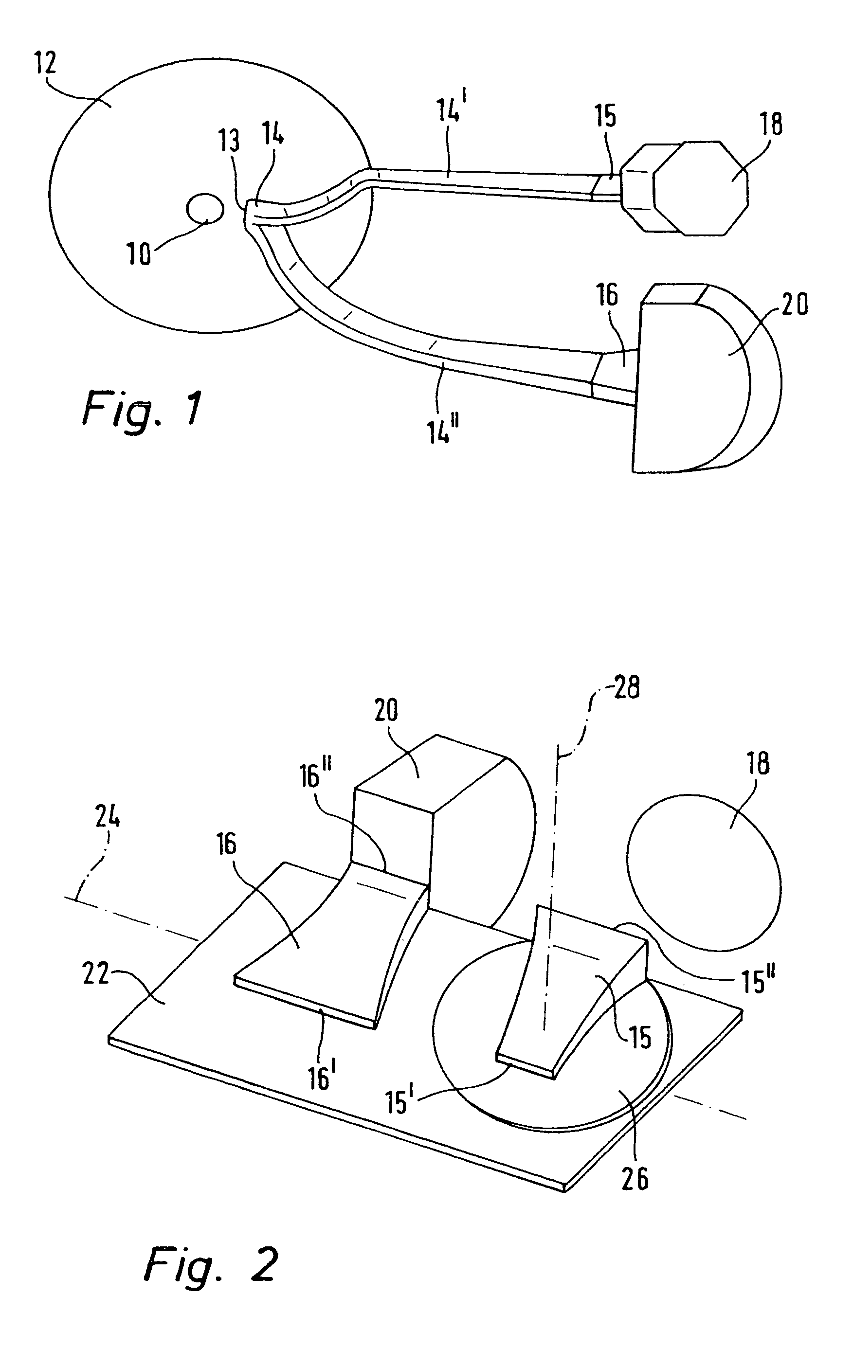
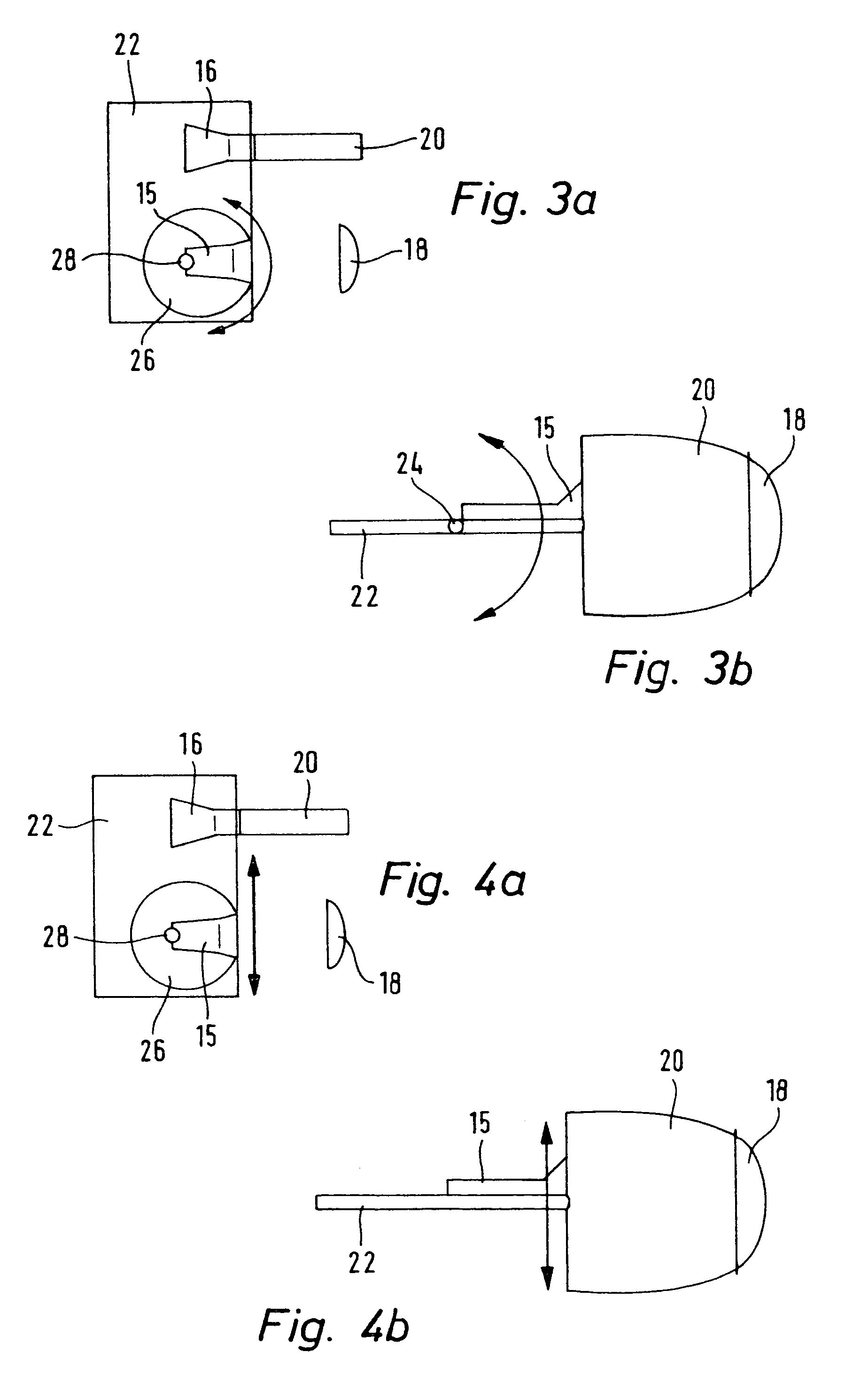
[0008]This object is achieved in accordance with the invention by a headlight, having at least one light terminator body fixed to or on a holder, the holder being pivotable about at least one axis and / or displaceable in at least one plane relative to the lens. In this manner, the lens may remain stationary relative to the bezel. In particular, the bezel and the lens or several lenses may be produced in one part or be connected to form one part to reduce the gap width to zero.

Problems solved by technology

However, this is not desired or required in most cases.

Method used


Image

  • Headlights for vehicles
  • Headlights for vehicles
  • Headlights for vehicles

Examples


Embodiment Construction

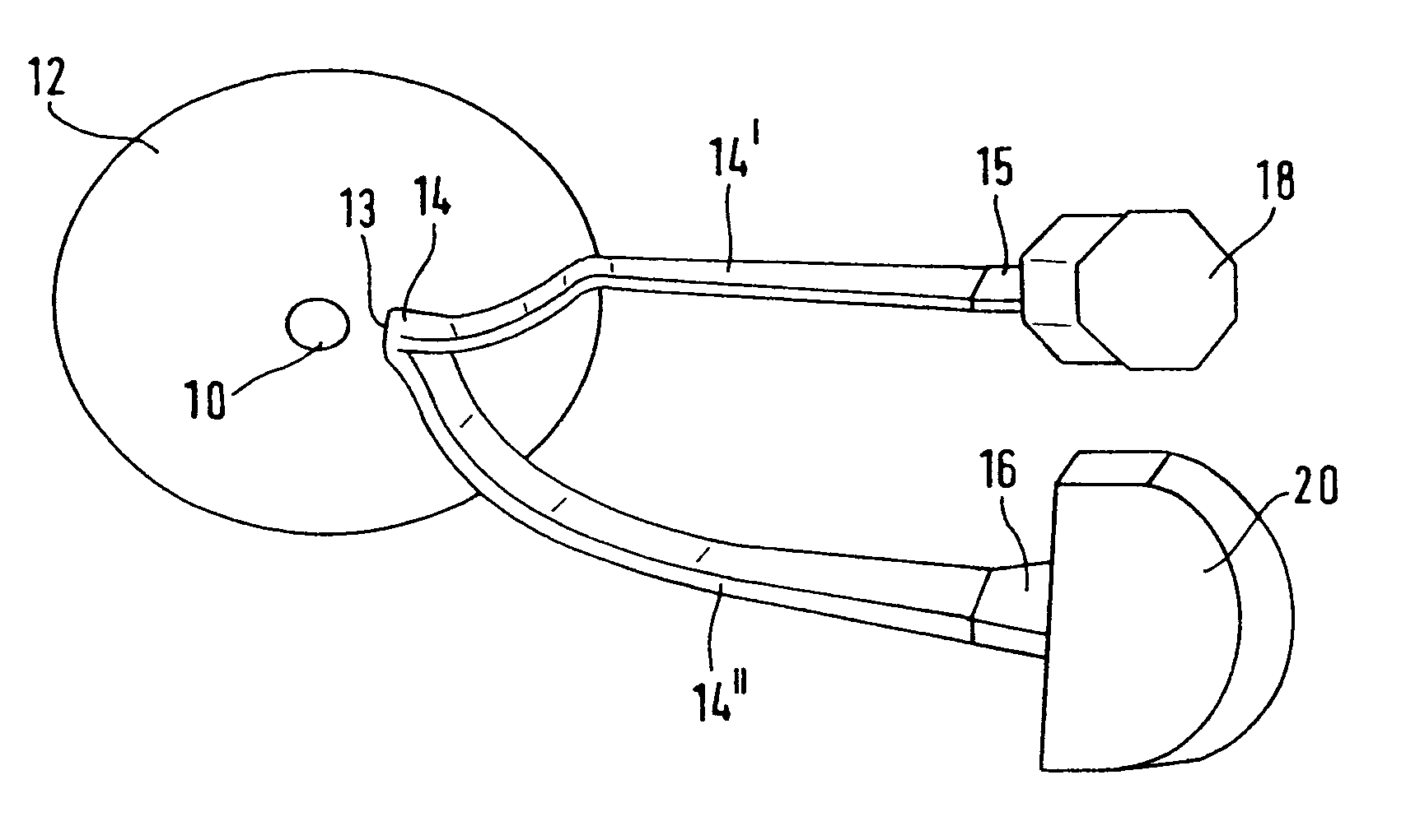
[0028]FIG. 1 shows a section or part of a conventional headlight comprising a light source 10 and a reflector 12 which focuses the light emitted by the light source onto a light coupling surface 13 of a light guide 14, which is divided into two light guiding strands 14′ and 14″. Each light guiding strand 14′ and 14″ leads to one light terminator body 15 or 16 which are each tightly connected to a lens 18 and 20, respectively. The lenses 18, 20 may have different designs in dependence on the light distribution to be generated as is produced through imaging of the light terminator body 15 or 16. The light is thereby fed from the light source 10 via the reflector 12 into the light coupling surface 13 of the light guide arms 14′ and 14″ where it is further guided through total internal reflection to the light terminator bodies 15 or 16. The light terminator bodies 15 and 16 have light output surfaces (not shown) whose cross-section is designed to emit substantially the desired light dis...


PUM


Abstract

Headlight for motor vehicles, comprising at least one light source and at least one light guide associated with each light source, into which the light emitted by the light source can be coupled via a light coupling surface, wherein each light guide is associated with a light terminator body into which the light from the light guide is passed, wherein the light terminator body has a light output surface and the output light can be imaged through a downstream lens, wherein the at least one light terminator body is fixed on or to a holder and the holder can be pivoted about at least one axis and / or be displaced in at least one plane relative to the at least one lens.

Description

[0001]This application claims Paris Convention priority of DE 103 25 330.0 filed Jun. 4, 2003 the complete disclosure of which is hereby incorporated by reference.BACKGROUND OF THE INVENTION[0002]The invention concerns a headlight for motor vehicles, comprising at least one light source and at least one light guide, associated with each light source, into which the light emitted by the light source can be coupled via a light coupling surface, wherein each light guide is associated with a light terminator body in which the light from the light guide can be further guided, wherein the light terminator body has a light output surface and the output light can be imaged by a downstream lens.[0003]DE 41 39 267 A1 discloses e.g. a headlight for motor vehicles, comprising at least two light sources which are formed as light emitting surfaces of at least one light guide. Towards this end, the light is guided from a light source through the light guide to a location where it is irradiated and...

Claims


Application Information

Patent Timeline
Patent Type & Authority Patents(United States)
IPC IPC(8): F21V9/00F21S8/10F21V21/14F21V5/00G02B6/04F21S8/12F21V14/00F21V14/06
CPCF21S48/1241F21V14/00F21S48/1721F21S41/24F21S41/635
Inventor GEBAUER, MATTHIAS
Owner AUTOMOTIVE LIGHTING REUTLINGEN GMBH
Learn More