
Variable pressure-controlled cooling scheme and thrust control arrangements for a steam turbine

a steam turbine and variable pressure control technology, which is applied in the direction of machines/engines, engine starters, liquid fuel engines, etc., can solve the problems of multiple reheat stages, difficult to accept multiple and repeated directional changes in thrust, and difficult to ensure the reliability of steam turbine operation under these conditions

Inactive Publication Date: 2007-03-27
GENERAL ELECTRIC CO
View PDF3 Cites 21 Cited by
  • Summary
  • Abstract
  • Description
  • Claims
  • Application Information

AI Technical Summary

Benefits of technology

Enhances turbine reliability by protecting bearings from high-temperature steam, maximizes efficiency by optimizing cooling steam usage, and provides flexible thrust control, reducing the risk of thermal failure and extending machine lifespan.

Problems solved by technology

In turn, robust operation of steam turbines under these conditions can be problematic.
Some systems may not incorporate the IP section, and more complex systems may have multiple reheat stages.
An additional consideration associated with thrust bearings is that thrust bearings do not readily accept multiple and repeated directional changes in thrust due to the existence of a near-zero thrust region wherein the bearing may become metastable.
Their ability to rapidly absorb directional reversals in thrust is limited.
It is noted herein that substantial damages may occur when steam turbine bearings fail.
Therefore, it is a challenge to ensure that only acceptable pressures and temperatures of steam, including cooling steam, are present in appropriate parts of the system.
However, due to anomalies and also due to standard differences in operating conditions, the reliability of modern steam turbines can still be improved, i.e., start-up verses steady state, failure of the oil seals upon exposure to temperatures beyond design limits, extreme steam temperatures and pressures, vibration, bearing wear, and due to manufacturing variations and other anomalous conditions.

Method used


Image

  • Variable pressure-controlled cooling scheme and thrust control arrangements for a steam turbine
  • Variable pressure-controlled cooling scheme and thrust control arrangements for a steam turbine
  • Variable pressure-controlled cooling scheme and thrust control arrangements for a steam turbine

Examples


Embodiment Construction

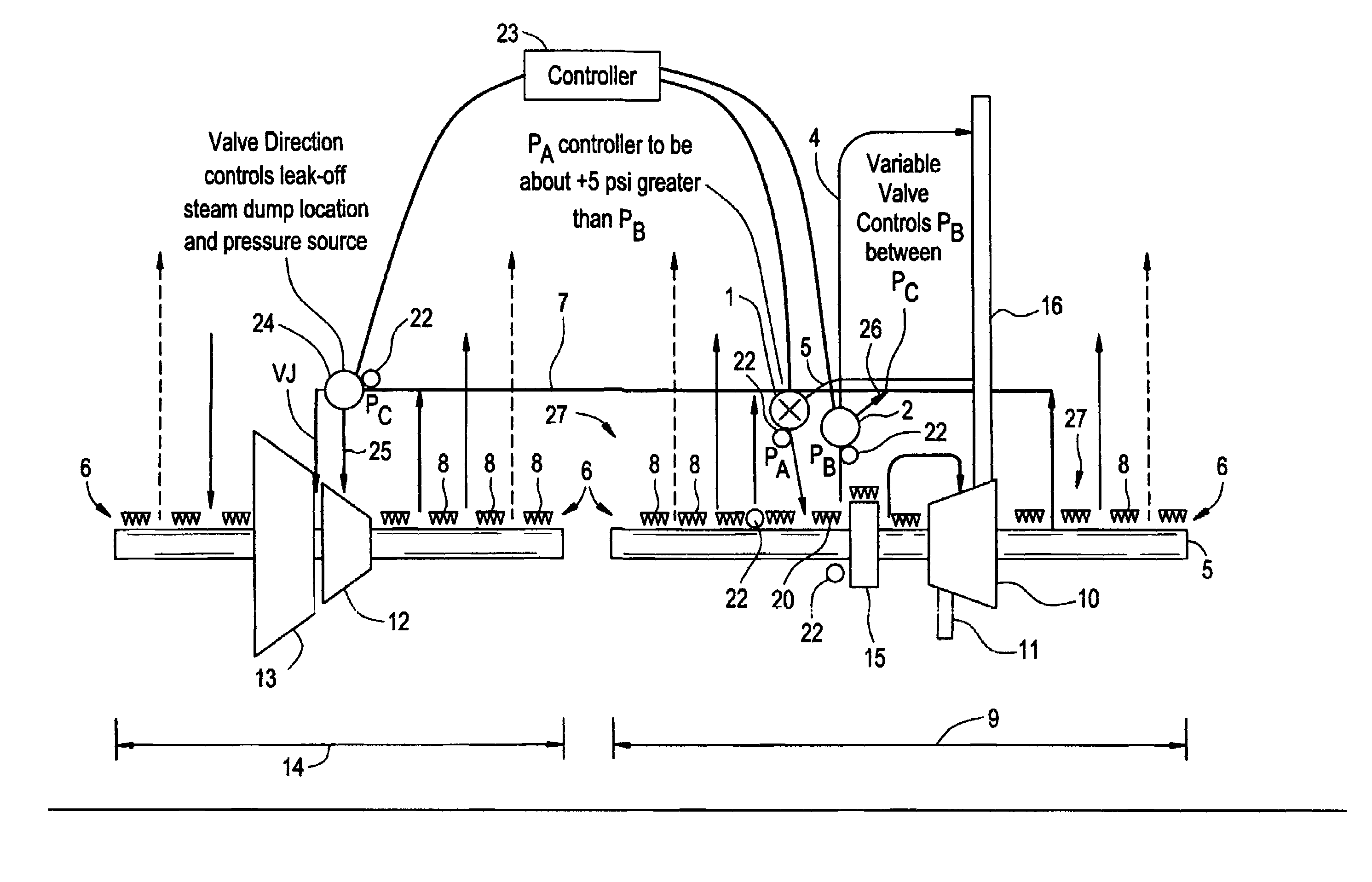
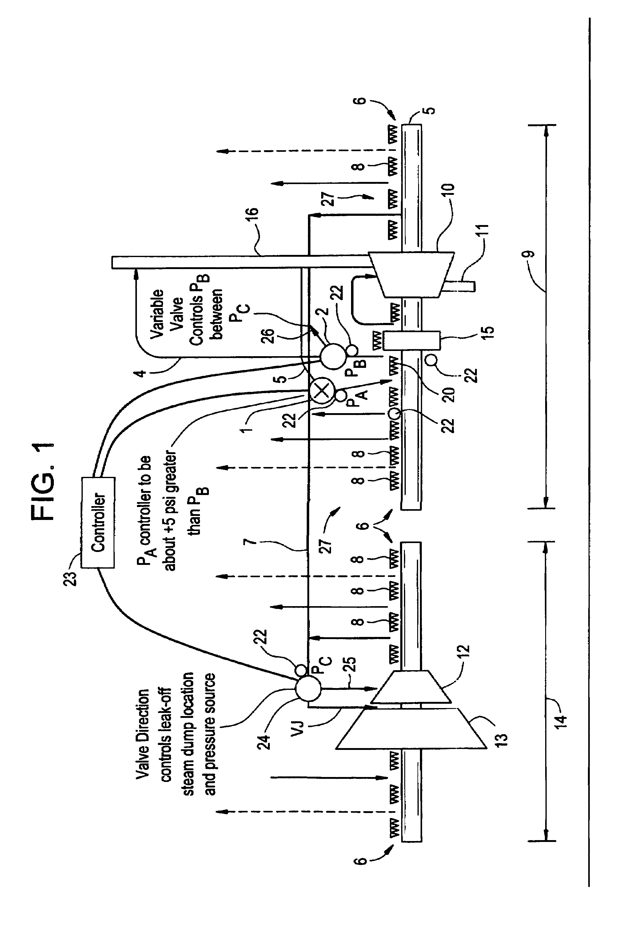
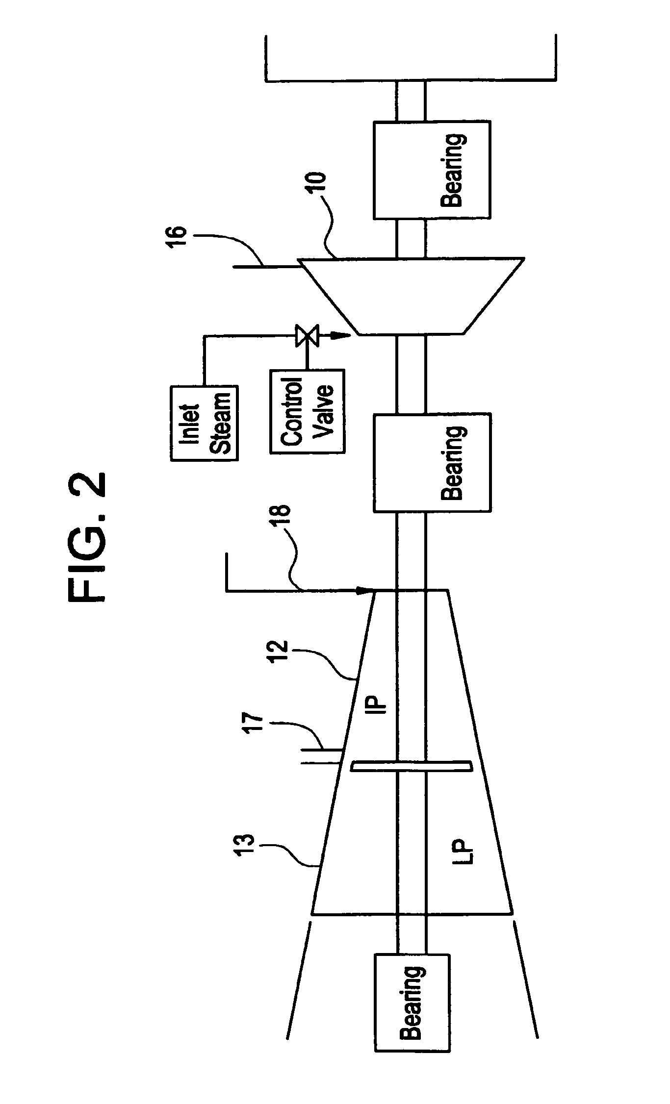
[0014]The present embodiment may include an active pressure barrier and thrust control system for a steam turbine and may be embodied as a physical control layer comprising arrangements of secondary piping and valves. This active control layer is suitable for use in a steam turbine having underlying primary steam turbine structures or sections which are well known. Thus, the entire structure of a known steam turbine subject to control by the present control system is not shown. It is noted herein that the control system is not limited to control of one particular type of steam turbine.

[0015]To illustrate this embodiment, a multi-stage steam turbine is used as the underlying turbine to be controlled. However, the concepts of the present invention would also be applicable to single stage steam turbines; thus, the underlying steam turbine structure should not be considered as limiting to the active control concepts described herein.

[0016]In multistage steam turbines, multiple “stages” ...


PUM


Abstract

A method and system for actively controlling thrust pressure in a steam turbine is disclosed. The method may comprise monitoring a thrust pressure affecting a thrust fitting in a steam turbine, and adjusting the thrust pressure to maintain a desired thrust pressure on the thrust fitting in the steam turbine.

Description

BACKGROUND OF THE INVENTION[0001]Steam turbines have been commonly applied to generation of mechanical or electrical power for over one hundred years. The standard cycle is based upon a source of heat energy to generate steam, a turbine, a water or air cooled condenser for heat rejection, and a pumping system. Steam turbines are highly efficient as the expansive force of steam is the greatest of any of the common gases used for powering turbines. Steam turbines also benefit from use of an inexpensive, plentiful, and environmentally friendly working fluid. Thus, steam turbines are used in many applications.[0002]However, achievement of the highest possible efficiencies requires that high temperatures and high pressures be utilized. In turn, robust operation of steam turbines under these conditions can be problematic. For example, inlet temperatures and pressures of 1400 degrees Fahrenheit (760° C.) and 5600 psi have been used. Common conditions for a modern boiler and steam turbine s...

Claims


Application Information

Patent Timeline
Patent Type & Authority Patents(United States)
IPC IPC(8): F01D3/04
CPCF01D3/02F01D3/04F01D17/12F05D2240/52F05D2270/301F05D2220/31F05D2270/3015F05D2270/051F05D2240/56
Inventor VANDERVORT, CHRISTIAN LEEKIM, JE-HOON
Owner GENERAL ELECTRIC CO
Learn More