Connector, and portable terminal equipment including the connector

a technology of connectors and portable terminals, applied in the direction of coupling contact members, coupling device connections, electric discharge lamps, etc., can solve the problems of inefficiency of removal of foreign matter, bad connection between the receptacle and the plug, and the impact of each receptacle contact and the associated plug contact, etc., to achieve stable contact resistance

Active Publication Date: 2007-03-27
KYOCERA CORP
View PDF14 Cites 37 Cited by
  • Summary
  • Abstract
  • Description
  • Claims
  • Application Information

AI Technical Summary

Benefits of technology

[0013]It is desirable for the second projecting portion to be formed on the contacting portion to be inclined with respect to the contacting portion to increase a distance between the second projecting portion and the contact projecting portion in a direction from one end of the second projecting portion which is formed integral with the first projecting portion to the other end of the second projecting portion when the plug is plugged into and unplugged from the receptacle.
[0019]According to the present invention, foreign matter between the plug and the receptacle can be removed securely and easily because the wide first projecting portion is in sliding contact with the contact projecting portion in a wide range and further because at least one second projecting portion is in sliding contact with the contacting projecting portion while imposing a strong load on the contact projecting portion in a concentrated manner. Moreover, even if each plug contact and the associated receptacle contact are not precisely positioned relative to each other when the plug is plugged into the insertion groove of the receptacle, the contact resistance between the plug and the receptacle becomes stable because a portion of the contact projecting portion which is in sliding contact with the contacting portion when the plug is plugged into the insertion groove of the receptacle is formed as a flat surface. Furthermore, even if the plug is plugged and unplugged into and from the receptacle many times, there is little possibility of foreign matter accumulating between the receptacle and the plug, and accordingly, a stable contact resistance between the plug and the receptacle is achieved because no recess or gap is formed between the first projecting portion and the second projecting portion by the arrangement wherein one end the second projecting portion is formed integral with the first projecting portion.

Problems solved by technology

A conventional connector including a receptacle and a plug which are engaged with each other to be electrically connected to each other by inserting the plug into an insertion groove formed on the receptacle has a structural problem such that foreign matter easily accumulates between contacts of the receptacle and associated contacts of the plug, i.e., between two opposed arrays of contacts of the receptacle (receptacle contacts), which are arranged on opposed inner walls in the insertion groove of the receptacle, and associated two arrays of contacts of the plug (plug contacts), which are arranged on opposite sides of the plug to be capable of being in contact with the two opposed arrays of receptacle contacts, respectively, thus causing a bad connection between the receptacle and the plug.
However, since each receptacle contact and the associated plug contact are in surface contact with each other when the plug is connected to the receptacle, it is difficult to make each receptacle contact and the associated plug contact impose loads on each other in a concentrated manner, and accordingly, such foreign matter cannot be removed efficiently by repeatedly plugging and unplugging the plug into and from the receptacle.
However, if the plug and the receptacle are not precisely positioned relative to each other when the plug is plugged into the receptacle, there is a possibility of the contact projecting portion and the recessed portion being in contact with each other at only one point, or there is a possibility of the contact projecting portion not being engaged in the recessed portion.
If the contact projecting portion and the recessed portion are in contact with each other at only one point, a sliding contact between the contact projecting portion and the recessed portion occurs only at a single point (on a single line), which tends to be incapable of removing foreign matter thoroughly, so that there is a possibility of the contact resistance between the plug and the receptacle becoming unstable.
Moreover, if the contact projecting portion does not slip into the recessed portion but rather slides on a flat surface portion on the contacting portion on which the recessed portion is not formed, foreign matter is not trapped into the recessed portion and merely moves on the flat surface portion by insertion / extraction movements of the plug relative to the insertion groove of the receptacle, and accordingly, such foreign matter cannot be removed to a sufficient degree.
Furthermore, miniaturization of such a conventional connector reduces the contact pressure between each contacting portion and the associated contact projecting portion, thus causing instability of the contact resistance between the plug and the receptacle.
If the contact projecting portion is replaced with a flat shaped or a substantially flat shaped contact portion so that each contact portion becomes capable of coming in surface contact with the associated contacting portion, it becomes difficult to make each receptacle contact and the associated plug contact impose loads on each other in a concentrated manner when the plug and the receptacle come in contact with each other, and therefore the efficiency of removing foreign matter decreases.
Such accumulated foreign matter makes it difficult for the contact projecting portion to enter the associated recessed portion, and also makes it difficult for newly-removed foreign matter to be trapped into the recessed portion; additionally, the contact resistance between the plug and the receptacle becomes unstable because foreign matter trapped and accumulated in the recessed portion is not removed therefrom.
On the other hand, if foreign matter is adhered to the recessed portion before the plug is plugged into the receptacle, such foreign matter tends to get trapped deeply into the recessed portion due to plugging and unplugging the plug into and from the receptacle, which also causes instability of the contact resistance between the plug and the receptacle.

Method used


Image

  • Connector, and portable terminal equipment including the connector
  • Connector, and portable terminal equipment including the connector
  • Connector, and portable terminal equipment including the connector

Examples


Embodiment Construction

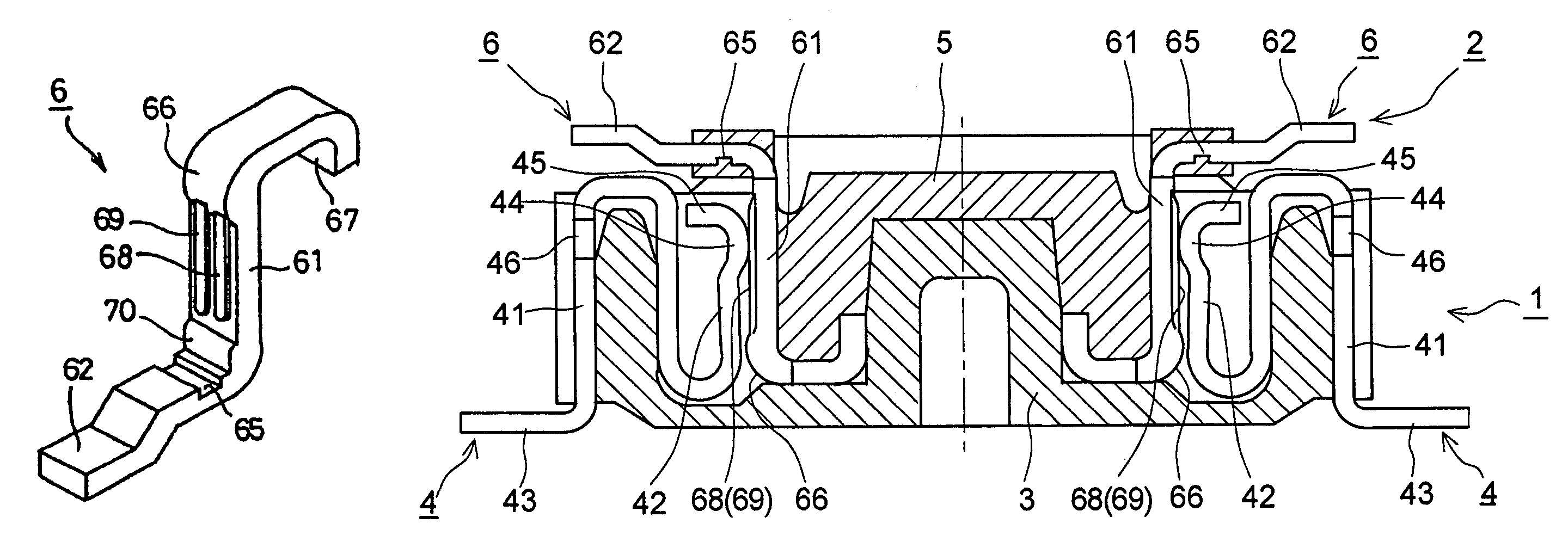
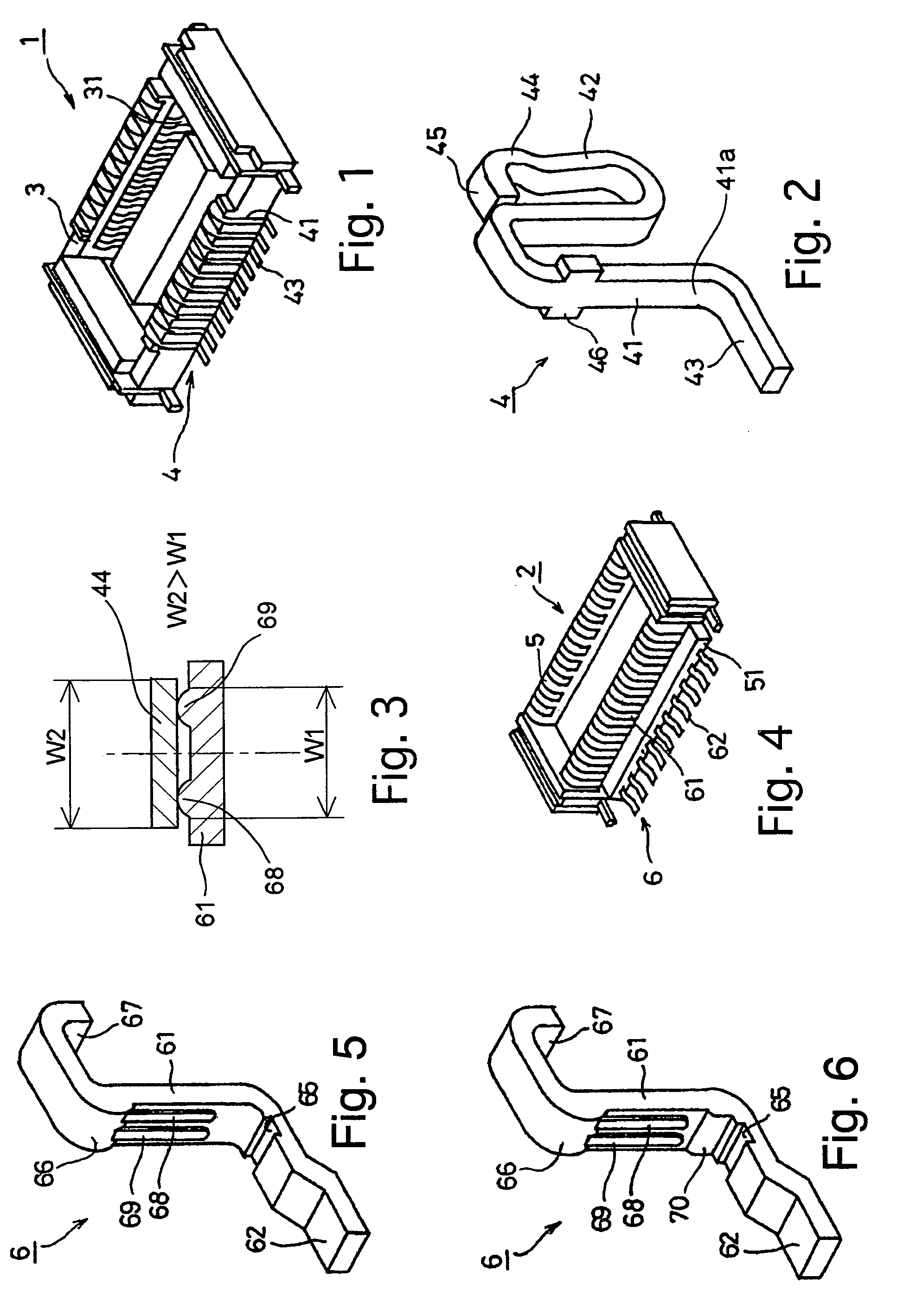
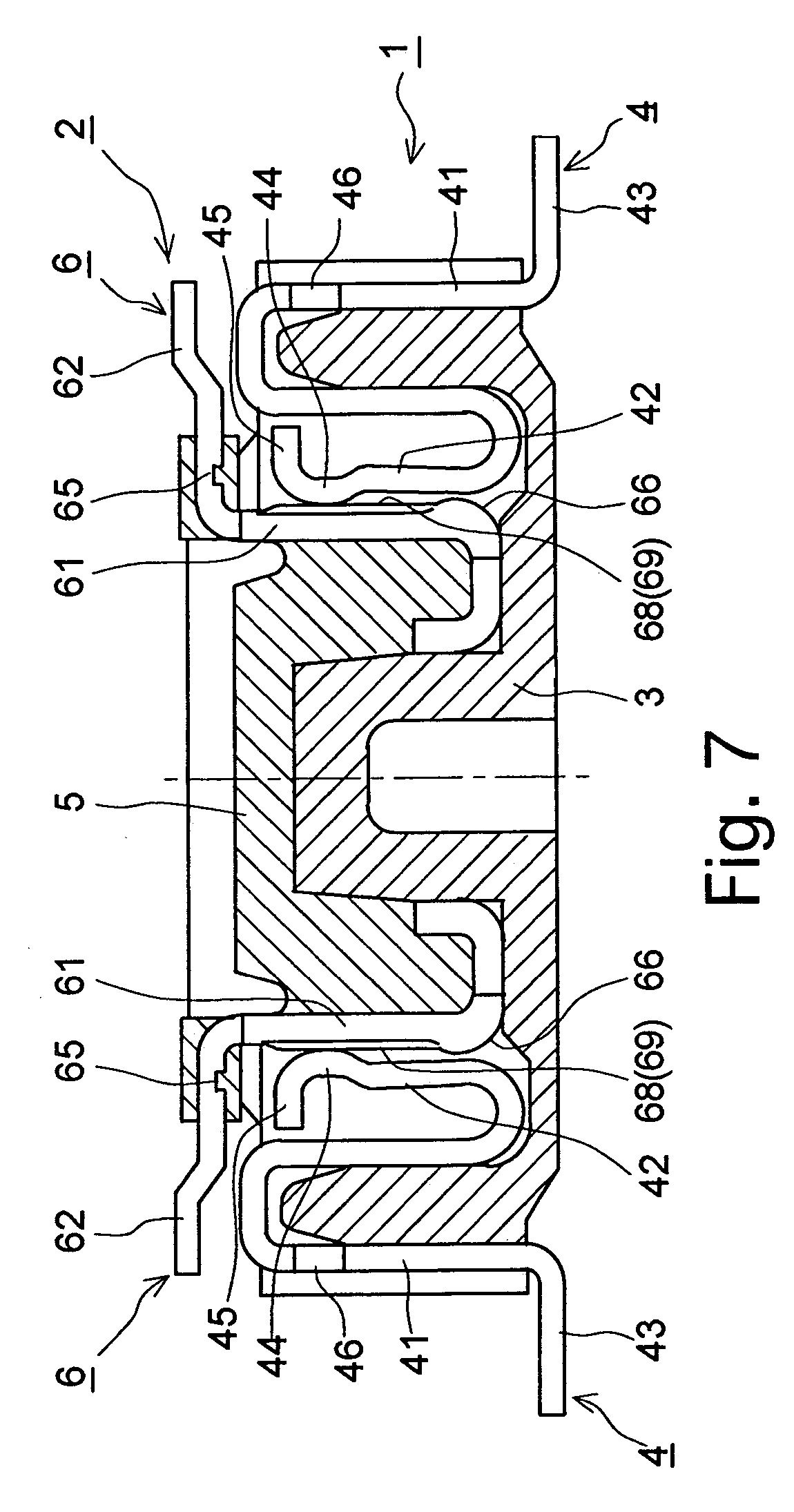
[0028]An embodiment of a connector according to the present invention is provided with a receptacle 1 shown in FIG. 1 and an associated plug 2 shown in FIG. 4 which are engaged with each other to be electrically connected to each other. For instance, one of the receptacle 1 and the plug 2 is mounted to an LCD (liquid display device / display device) unit or a CCD (charge coupled device / image pickup device) unit, while the other of the receptacle 1 and the plug 2 is mounted to a board (e.g., circuit board) which is electrically connected to the LCD unit or the CCD unit to control operations thereof. The LCD unit or the CCD unit is electrically connected to the board by the engagement of the plug 2 with the receptacle 1. The receptacle 1 and the plug 2 can be adopted for establishing electrical connection within portable terminal equipment (e.g., a cellular phone, a PDA (personal digital assistant) such as a mobile computer and the like) or electrical connection between portable termina...


PUM


Abstract

A connector includes a plug including a plug body made of an insulating material and at least one plug contact supported by the plug body; a receptacle including a receptacle body made of an insulating material and at least one receptacle contact supported by the receptacle body; a contact projecting portion formed on one of the plug contact and the receptacle contact; a contacting portion formed on the other of the plug contact and the receptacle contact; and a first projecting portion and at least one second projecting portion which is formed on the contacting portion, the second projecting portion being formed integral with the first projecting portion to be elongated in an insertion / extraction direction of the plug. A portion of the contact projecting portion is formed as a flat surface having a width greater than a width of the second projecting portion.

Description

CROSS REFERENCE TO RELATED APPLICATION[0001]The present invention is related to and claims priority of the following co-pending application, namely, Japanese Patent Application No. 2004-240018 filed on Aug. 19, 2004.BACKGROUND OF THE INVENTION[0002]1. Field of the Invention[0003]The present invention relates to a connector including a receptacle and a plug which are engaged with each other to be electrically connected to each other.[0004]2. Description of the Prior Art[0005]A conventional connector including a receptacle and a plug which are engaged with each other to be electrically connected to each other by inserting the plug into an insertion groove formed on the receptacle has a structural problem such that foreign matter easily accumulates between contacts of the receptacle and associated contacts of the plug, i.e., between two opposed arrays of contacts of the receptacle (receptacle contacts), which are arranged on opposed inner walls in the insertion groove of the receptacle...

Claims


Application Information

Patent Timeline
Patent Type & Authority Patents(United States)
IPC IPC(8): H01R12/00
CPCH01R12/716H01R2201/16H01R13/04
Inventor TAKANO, HIROHISASHIROYAMA, YUUSUKE
Owner KYOCERA CORP
Why Eureka
Try Eureka