Rotary electric machine

a rotary electric machine and electric motor technology, applied in the field of rotary electric machines, can solve the problems of not being able to directly wind the enameled wire around a plurality of teeth, and the space factor of the space occupied by the coil to the whole available space around the stator teeth is not satisfactorily high, and achieves a satisfactory space ratio. , the effect of easy mounting of the stator coil

Active Publication Date: 2007-03-27
DENSO CORP
View PDF18 Cites 19 Cited by
  • Summary
  • Abstract
  • Description
  • Claims
  • Application Information

AI Technical Summary

Benefits of technology

[0006]The present invention has been made to provide a rotary electric machine that

Problems solved by technology

However, it is not easy to directly wind the enameled wire around a plurality of teeth, and, therefore, the ratio (space f

Method used


Image

  • Rotary electric machine
  • Rotary electric machine
  • Rotary electric machine

Examples


Embodiment Construction

[0038]A rotary electric machine according to a preferred embodiment of the invention will be described with reference to the appended drawings.

[0039]The rotary electric machine is applied to a gearshift control unit that includes a gear shift mechanism and a parking mechanism to provide torque for gear shifting.

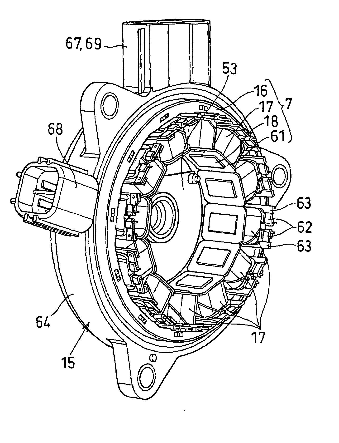
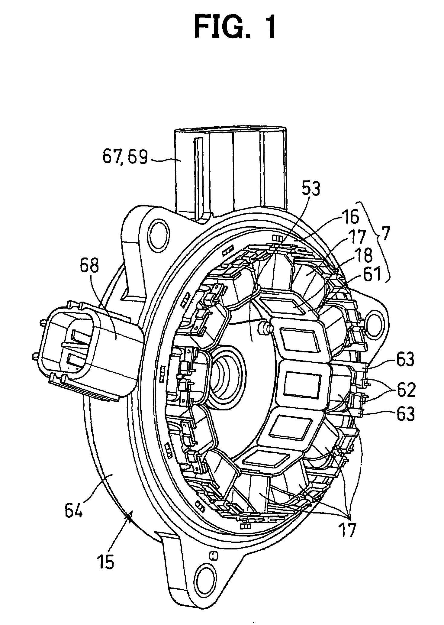
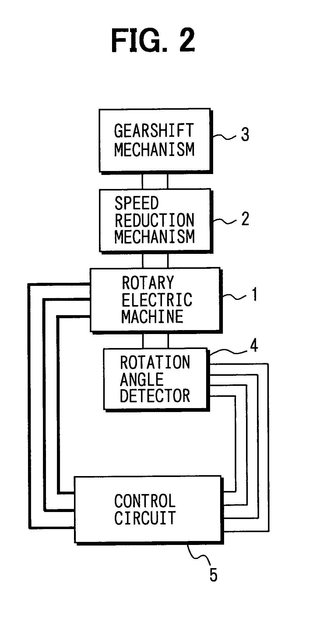
[0040]As shown in FIG. 2, the gearshift control unit includes the rotary electric machine 1, a speed reduction mechanism 2, a gearshift mechanism 3, a rotation angle detector 4 and a control circuit 5. The control circuit 5 controls the rotation angle of the rotary electric machine 1 by the rotation angle detector 4, thereby controlling the gearshift mechanism 3 that is driven via the speed reduction mechanism 3.

[0041]The rotary electric machine 1 is a synchronous motor that drives the gearshift mechanism 3. As shown in FIGS. 3 and 4, the rotary electric machine 1 includes a rotor 6 and a stator 7, which are disposed to be coaxial to each other.

[0042]The rotor 6 is constitute...


PUM

PropertyMeasurementUnit
Diameteraaaaaaaaaa

Abstract

In a rotary electric machine, each stator coil includes a bobbin that is fitted to one of teeth of a stator core and a phase coil is wound around the bobbin. Each bobbin includes a bobbin terminal for connecting opposite ends of the phase coil. A stator housing includes an insert mold and a plurality of stator terminals embedded in the insert mold to be connectable to an outside electric device. Each stator terminal has a first contact portion and each bobbin terminal has a second contact portion in contact with the first contact portion when the stator core is accommodated in the stator housing.

Description

CROSS REFERENCE TO RELATED APPLICATION[0001]The present application is based on and claims priority from Japanese Patent Application 2002-203208, filed Jul. 11, 2002, the contents of which are incorporated herein by reference.BACKGROUND OF THE INVENTION[0002]1. Field of the Invention[0003]The present invention relates to an rotary electric machine, such as a motor or a generator and, particularly, a stator and a stator housing of the rotary electric machine.[0004]2. Description of the Related Art[0005]The stator of a known rotary electric machine is constituted of a plurality of stator teeth and a plurality of stator coils of an enameled wire that is directly wound the teeth. Usually, the ends of the stator coils are collected or bundled to be connected to a connector to be connected to an outside device. However, it is not easy to directly wind the enameled wire around a plurality of teeth, and, therefore, the ratio (space factor) of the space occupied by the coils to the whole ava...

Claims


Application Information

Patent Timeline
IPC IPC(8): H02K19/10H02K3/46H02K3/52H02K5/00H02K5/08H02K5/15H02K5/173H02K5/22H02K29/08
CPCH02K3/522H02K5/00H02K5/08H02K5/15H02K5/225H02K29/08H02K5/1732Y10T29/49009H02K2203/03Y10T29/49012
Inventor KIMURA, KIYOSHIYOSHIYAMA, SHIGERUHORI, MASASHI
Owner DENSO CORP
Why Eureka
Try Eureka