Eureka AIR delivers breakthrough ideas for toughest innovation challenges, trusted by R&D personnel around the world.

Tuner integrated circuit and television tuner using the same circuit

a technology of integrated circuit and television tuner, which is applied in the direction of television system, cross-talk/noise/interference reduction, and discrete tuning with seperate pre-tuned circuits, etc., and can solve problems such as interfering with normal reception

Inactive Publication Date: 2007-03-27
ALPS ALPINE CO LTD
View PDF7 Cites 1 Cited by
  • Summary
  • Abstract
  • Description
  • Claims
  • Application Information

AI Technical Summary

Benefits of technology

This patent describes systems and techniques for tuner electronics. The invention aims to prevent interference between circuits and reduce interference between peripheral circuits when the circuit is mounted on a printed circuit board. The patent also describes a tuner IC that prevents a reference oscillation signal from being transmitted to other terminals. The patent further describes a printed circuit board on which the tuner IC is mounted, which includes wiring conductors to prevent leakage of the reference oscillation signal. The technical effects of this patent include improved performance and reliability of tuner electronics.

Problems solved by technology

16, and superimpose on the signals and the voltages output from such terminals, thereby interfering with the normal reception.

Method used


Image

  • Tuner integrated circuit and television tuner using the same circuit
  • Tuner integrated circuit and television tuner using the same circuit
  • Tuner integrated circuit and television tuner using the same circuit

Examples


Embodiment Construction

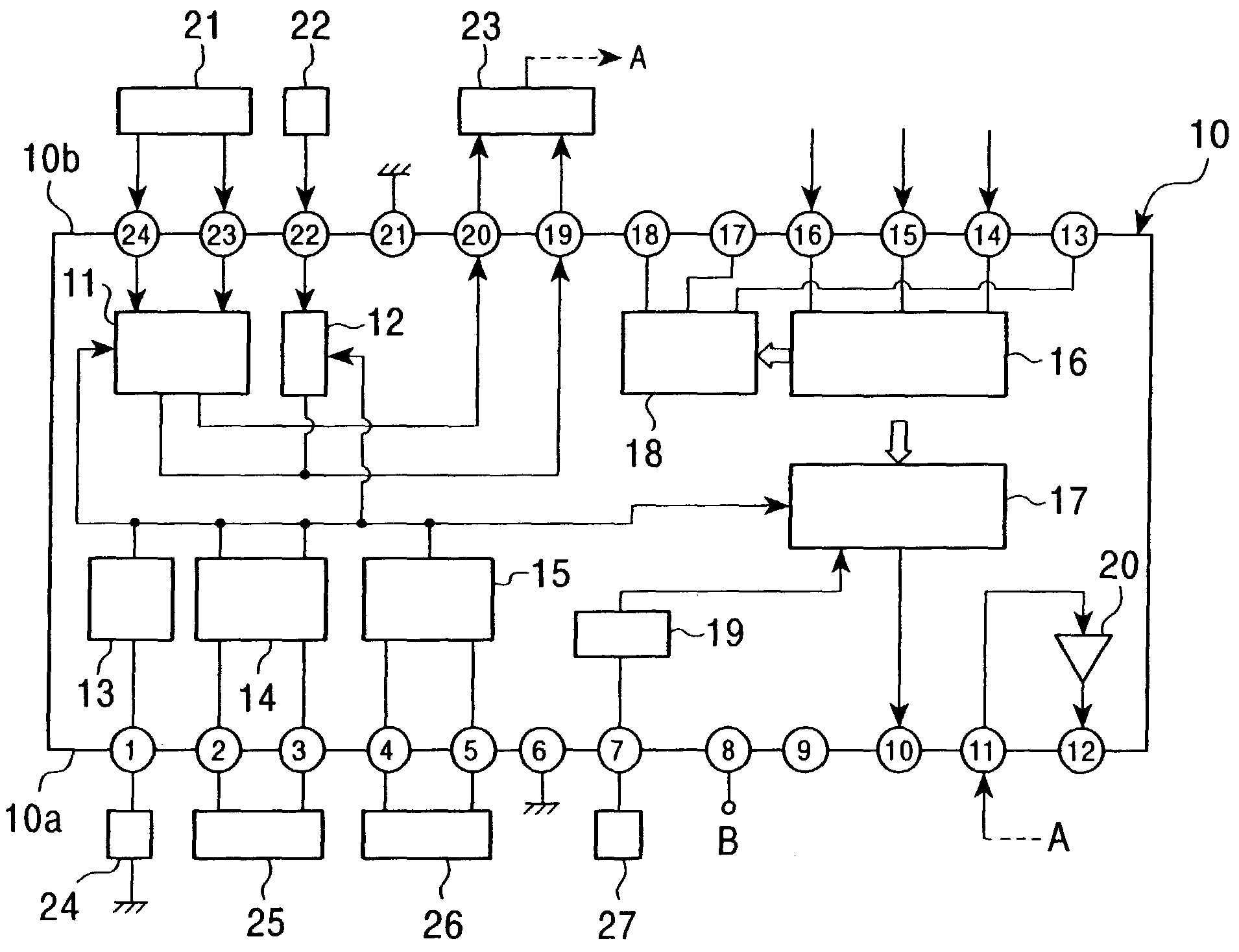
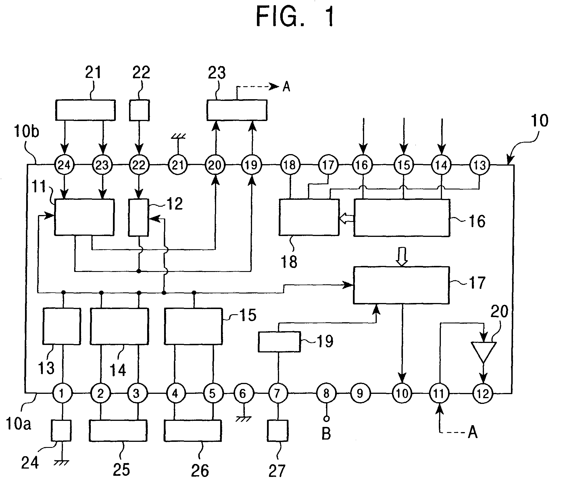
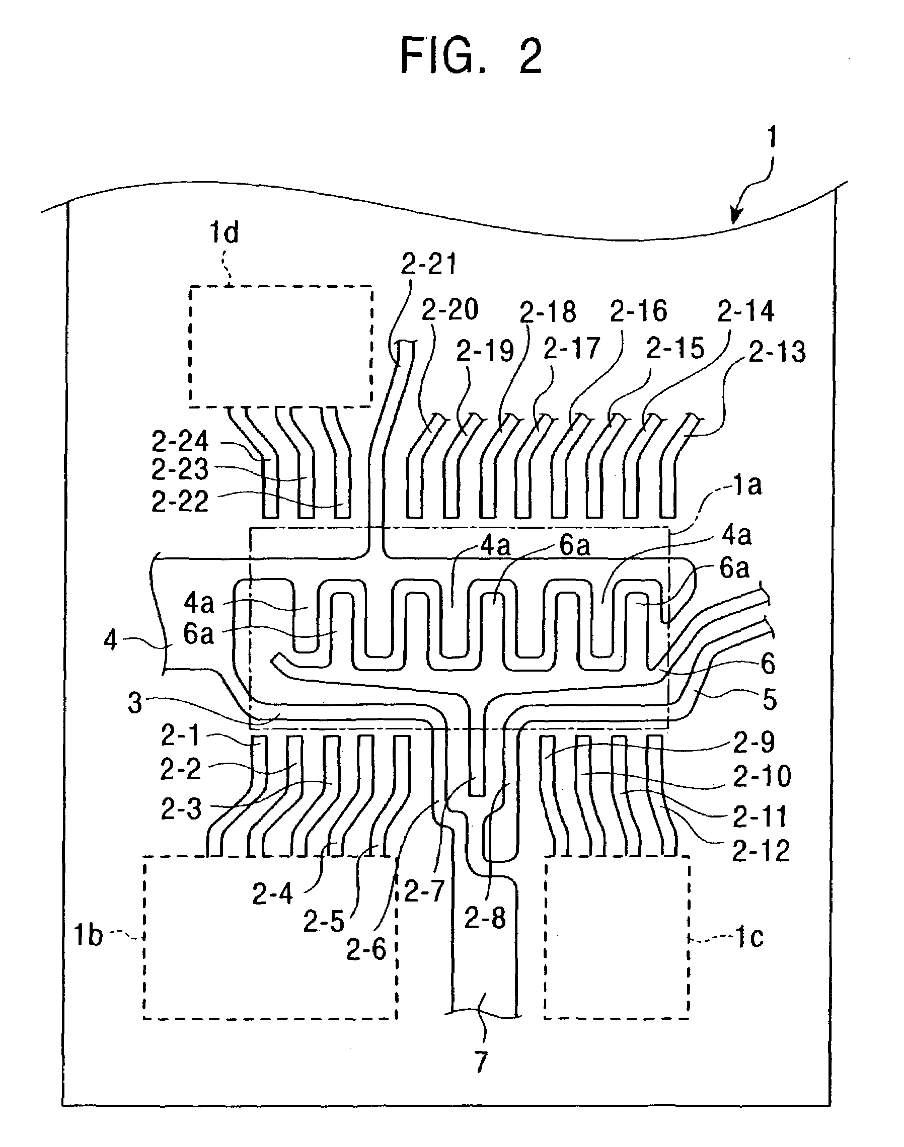
[0022]The circuit configuration and the relationship between the arrangement of terminals of a tuner IC 10 and the peripheral circuits are described below with reference to the schematic diagram of FIG. 1. The configuration of a television tuner using the IC 10 is shown in FIG. 2.

[0023]As shown in FIG. 1, the IC 10 has twelve terminals at each of two opposing sides. Terminals No. 1 through No. 12 are provided for one side 10a, while terminals No. 13 through No. 24 are provided for the other side 10b. A plurality of peripheral circuits, such as a VHF mixer circuit 11 and a UHF mixer circuit 12, are disposed inside the IC 10. The balanced input terminals of the VHF mixer circuit 11 are connected to terminals No. 23 and 24, and the input terminal of the UHF mixer circuit 12 is connected to terminal No. 22. The balanced output terminals of the VHF mixer circuit 11 and the UHF mixer circuit 12 are connected to terminals No. 19 and No. 20.

[0024]Local oscillation signals are supplied from ...


PUM


Abstract

One embodiment of a tuner integrated circuit includes two mixer circuits, an IF amplifier circuit, three oscillation circuits, a PLL circuit, and a reference oscillation circuit. A plurality of terminals are provided at two sides of the tuner integrated circuit and are connected to these elements. Among the terminals, at least an oscillator-connecting terminal for connecting an externally provided oscillator to the reference oscillation circuit, a power supply terminal through which a power supply voltage is supplied, and a ground terminal connected to a ground are provided at one side of the tuner integrated circuit. The power supply terminal and the ground terminal are disposed adjacent to the oscillator-connecting terminal such that they sandwich the oscillator-connecting terminal therebetween.

Description

BACKGROUND OF THE INVENTION[0001]1. Field of the Invention[0002]The present invention relates to a tuner integrated circuit and a television tuner using this integrated circuit.[0003]2. Description of the Related Art[0004]The circuit configuration and the relationship between the arrangement of terminals of a known tuner integrated circuit (hereinafter referred to as an “IC”) 30 and peripheral circuits are described below with reference to the schematic diagram of FIG. 3. As shown in FIG. 3, the IC 30 has sixteen terminals at each of the two opposing sides. Terminals No. 1 through No. 16 are provided for one side 30a, while terminals No. 17 through No. 32 are provided for the other side 30b. A plurality of peripheral circuits, such as a very high frequency (VHF) mixer circuit 31 and a ultrahigh frequency (UHF) mixer circuit 32, are disposed, as shown in FIG. 3, inside the IC 30. The balanced input terminals of the VHF mixer circuit 31 are connected to terminals No. 31 and No. 32, an...

Claims


Application Information

Patent Timeline
Patent Type & Authority Patents(United States)
IPC IPC(8): H04N5/50H03J5/24H04B1/26H04N5/44H05K1/02
CPCH05K1/0218H03J5/246
Inventor YAMAMOTO, MASAKI
Owner ALPS ALPINE CO LTD
Why Eureka
Eureka Blog
Learn More