Gauge assembly for measuring diameter and total indicated runout

a gauge assembly and measurement diameter technology, applied in the direction of mechanical diameter measurement, measurement devices, instruments, etc., can solve the problems of double the error potential of calibration of each gauge, difficult to do, and inability to accurately measure the diameter of the pointer gauge, etc., to achieve the effect of short tim

Inactive Publication Date: 2007-04-03
HONDA MOTOR CO LTD
View PDF17 Cites 32 Cited by
  • Summary
  • Abstract
  • Description
  • Claims
  • Application Information

AI Technical Summary

Benefits of technology

[0007]The present invention overcomes these and other disadvantages in the prior art. The present invention provides a single device that can measure both the diameter and runout on an article having a cylindric

Problems solved by technology

This is difficult to do because pointer gauge location is controlled by an advance/retraction system mounted to a machine table (as opposed to the air gauge position that is controlled by resting (in a datum condition) on the actual journal being measured).
2) The accuracy of the pointer gauges is susceptible to variations in the ambient temperature.
This introduces twice the error potential from ca

Method used


Image

  • Gauge assembly for measuring diameter and total indicated runout
  • Gauge assembly for measuring diameter and total indicated runout
  • Gauge assembly for measuring diameter and total indicated runout

Examples


Embodiment Construction

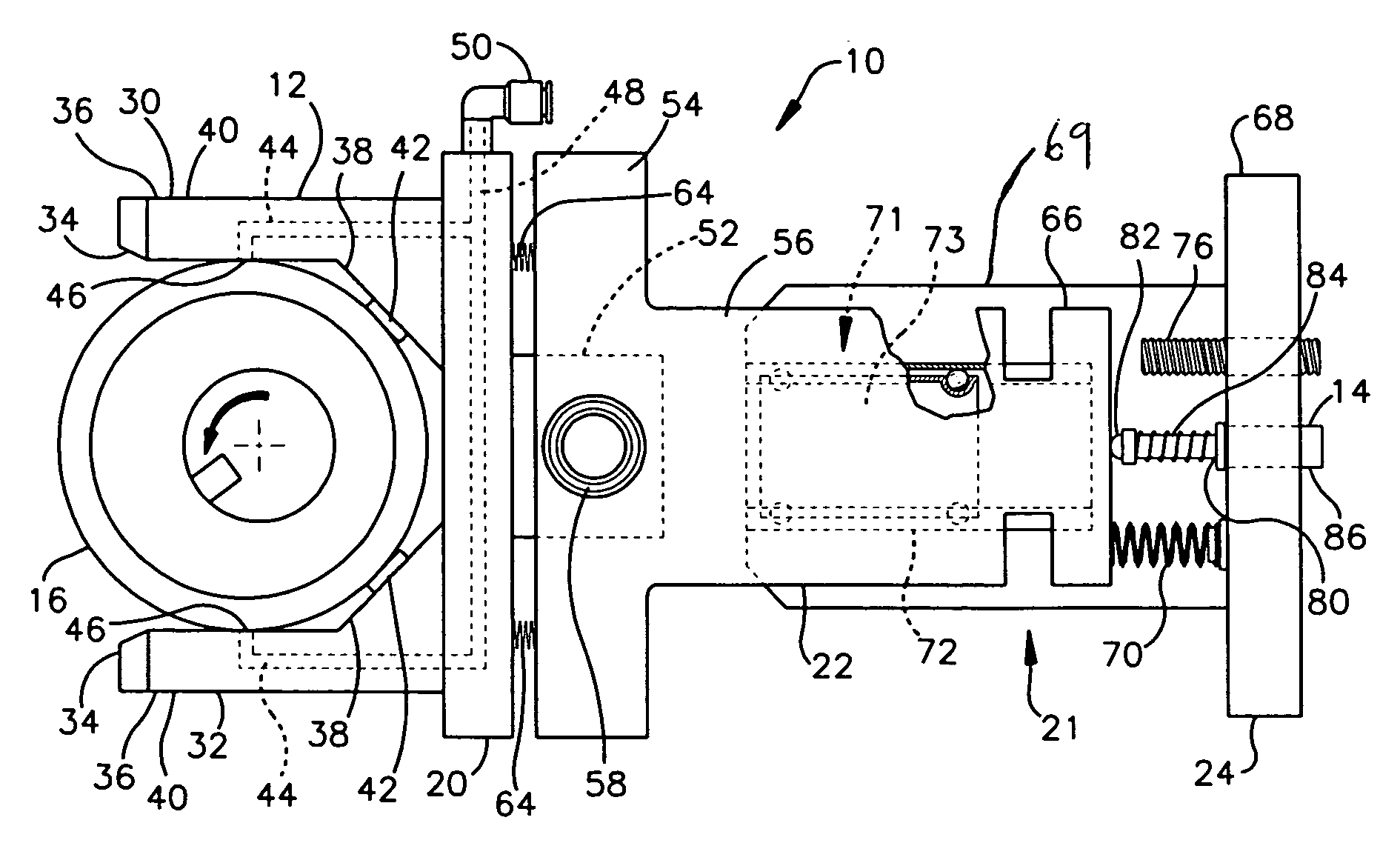
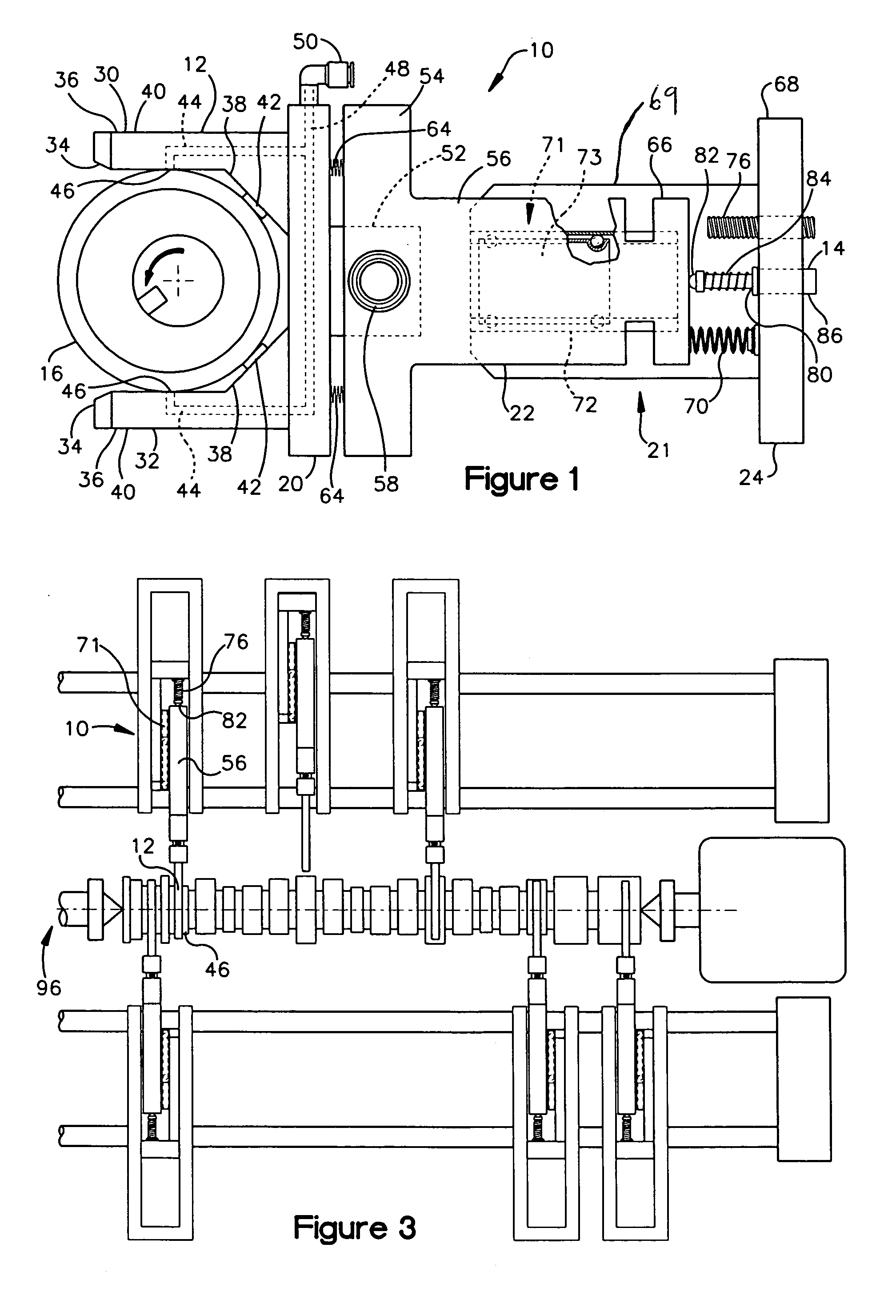
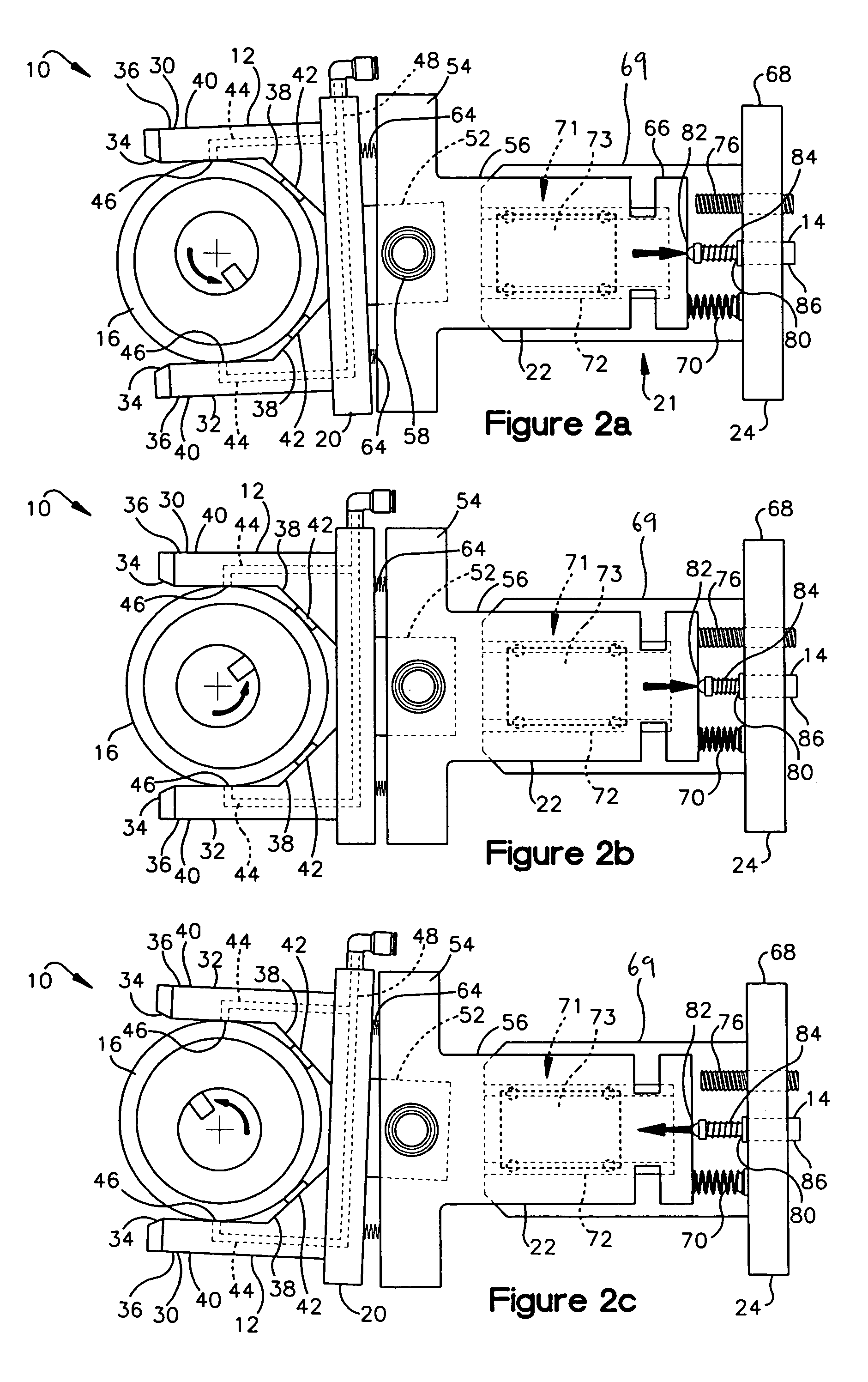
[0018]Referring to the drawings, specifically FIGS. 1 and 5, a preferred gauge assembly 10 for measuring diameter, roundness, and Total Indicated Runout (TIR) according to the present invention is illustrated. The gauge assembly 10 includes first and second gauges 12 and 14, the first gauge 12 for measuring the diameter of a generally cylindrical body 16 and the second gauge 14 for measuring TIR of the generally cylindrical body 16, such as the generally cylindrical journals on a camshaft. As described in more detail below, the first gauge 12 includes first and second arms 30 and 32 and a generally rectangular plate 20. The gauge assembly 10 also includes an interconnecting structure 21 for securing the first and second gauges 12, 14 together, the interconnecting structure including a neck portion 22 and base 24. The second gauge 14 is affixed to the base 24 and measures linear movement between the neck portion 22 and the base 24. Also described in more detail below, readings made b...


PUM


Abstract

The invention is directed to a gauge assembly that is used to measure parameters of camshaft journals or other objects with cylindrical surfaces. The gauge assembly includes two gauges, the first is an air snap gauge and the second a linear variable differential transducer. The air snap gauge is slidingly attached to the base and the second gauge is attached to a base as well. Air resistance measurements, taken through the air snap gauge provide a measure of diameter of the journal while relative linear motion between the base and air snap gauge, measured by the second gauge, provides a measure of journal runout relative to the center axis of the camshaft. Control logic is used to calculate other parameters such as runout of a journal relative to another journal on a common camshaft.

Description

BACKGROUND OF THE INVENTION[0001]Meeting camshaft design specification within an engine is critical in order to provide proper operation of the apparatus driven by that engine. Thus, each manufactured camshaft is tested to make sure critical dimensions are within a desired tolerance. The camshaft journals (round portions of the camshafts located between the cams, are typically checked for proper diameter, roundness and runout (the amount the journal deviates from the camshaft axis or another reference when rotated).[0002]Commonly, the diameter of the journal is measured using an air snap gauge. This gauge includes two arms, each with a straight section and an inwardly angling section, that extend along either side of the journal. The snap guage is advanced over the journal until the journal contacts a pad on the inner side of the inwardly angling section of each arm. When the journal contacts the two pads, slits on the straight section of each arm, are aligned on diametrically oppos...

Claims


Application Information

Patent Timeline
IPC IPC(8): G01B3/00
CPCG01B5/003G01B5/08G01B5/201
Inventor BLANFORD, WILLIAM C.GRIESHOP, DALE
Owner HONDA MOTOR CO LTD
Why Eureka
Try Eureka