

Coupling structure mountable to a rotatable shaft
a technology of coupling structure and rotatable shaft, which is applied in the direction of rotating vibration suppression, spring/damper, rotary machine parts, etc., can solve the problems of gear puller lateral force, other parts of the engine or cooling system, and the lateral force that must be applied by the gear puller during the removal is significan
- Summary
- Abstract
- Description
- Claims
- Application Information
AI Technical Summary
Benefits of technology
Problems solved by technology
Method used
Image

Examples
Embodiment Construction
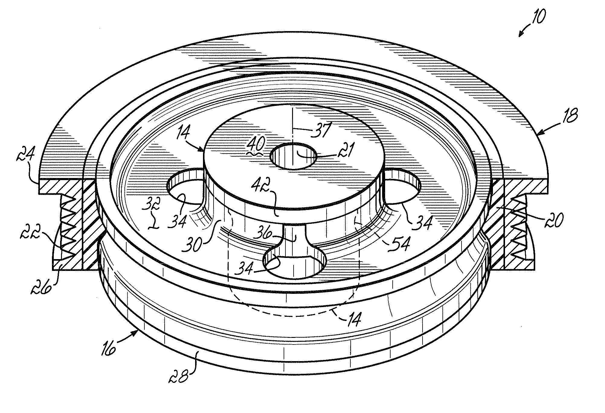
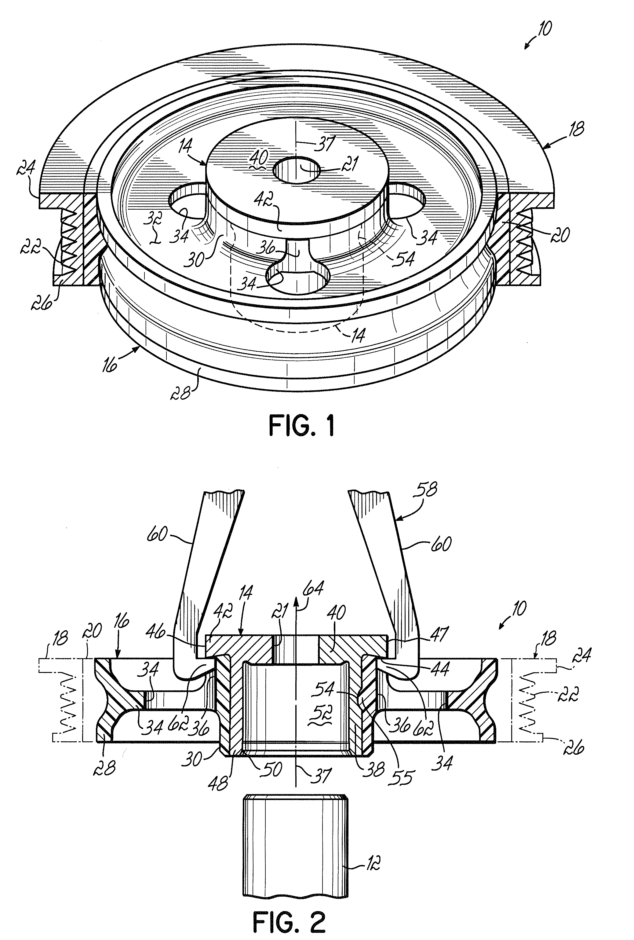
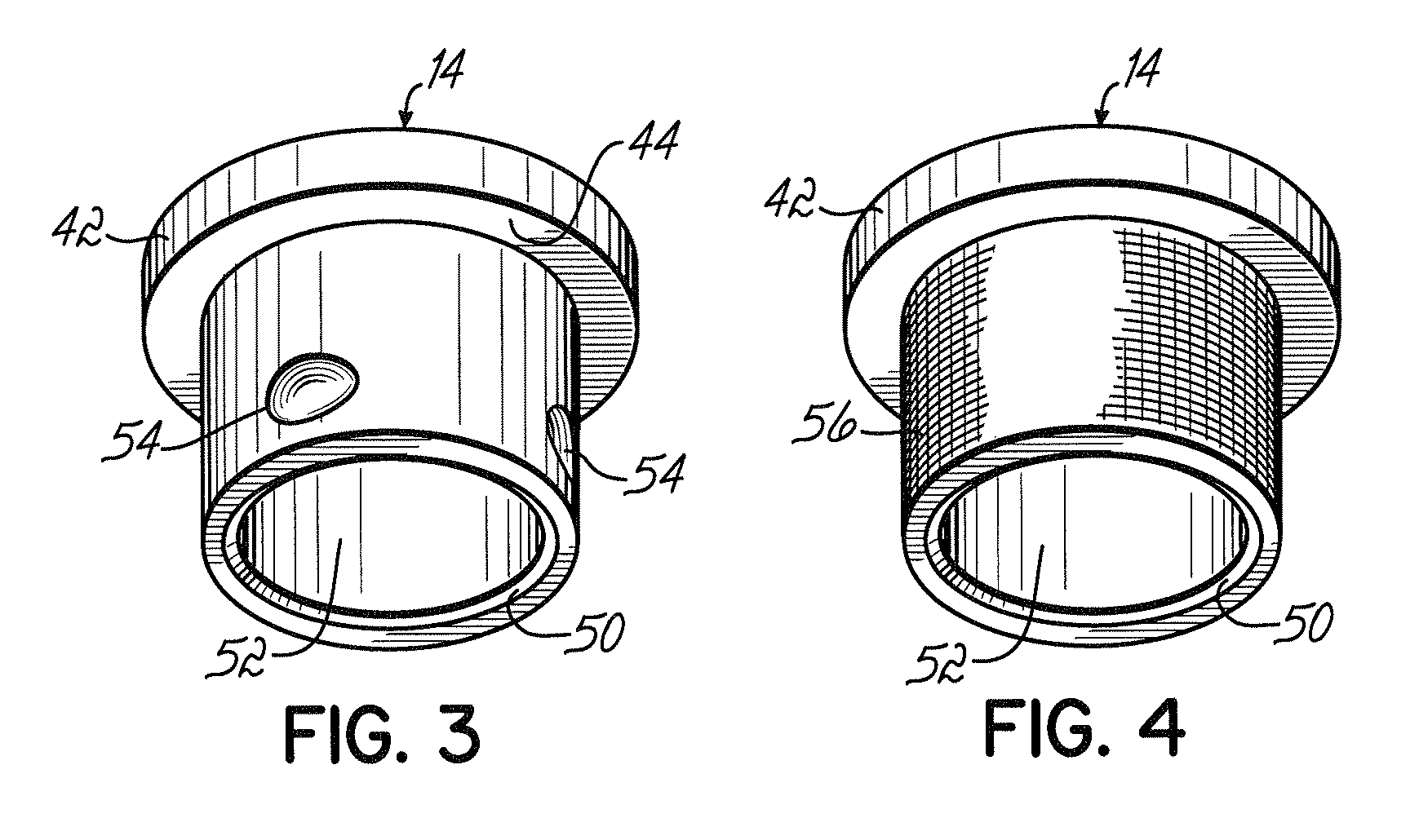
[0014]With reference to FIGS. 1–3, a torsional vibration damper, indicated generally by reference numeral 10, is shown mounted to one end of a rotatable shaft 12, such as the accessory end of a crankshaft opposite to the flywheel end, in an internal combustion engine. The torsional vibration damper 10 is assembled from a metallic insert 14, an annular polymer hub 16 disposed radially outward from the metallic insert 14, an inertia member 18 disposed radially outward from the polymer hub 16, and an annular elastomer layer 20 disposed radially in the space between the polymer hub 16 and the inertia member 18. The metallic insert 14 and the polymer hub 16, and typically the inertia member 18 and elastomer layer 20 as well, are arranged coaxially with a longitudinal axis 37 so that the structure is symmetrical about the longitudinal axis 37 and, as a result, balanced. The metallic insert 14 and annular polymer hub 16 collectively define a coupling structure for mounting the inertia memb...
PUM
 Abstract
Description
Claims
Application Information