Method of strengthening of moulds of aluminum or its alloy

a technology of aluminum or its alloy and mould walls, which is applied in the direction of cocoa, sweetmeats, dough shaping, etc., can solve the problems of increasing the number of rejected moulded items, the contact surfaces of the mould walls are worn and deformed to a certain extent, and the mould walls are deformed and worn, so as to prevent the deformation and wear of the mould walls and extend the service life of the mould in general.

Inactive Publication Date: 2007-04-03
LIEW KHONG FAH
View PDF3 Cites 1 Cited by
  • Summary
  • Abstract
  • Description
  • Claims
  • Application Information

AI Technical Summary

Benefits of technology

[0004]Various methods are introduced in the present invention to prevent the deformation and wear of the mould walls and hence extend the service life of the mould in general. One method includes introducing an insert or a plurality of inserts in each of the mould walls to react majority of the moulding pressures encountered in the moulding process. These inserts are made of a material or materials that is stronger than the base material of the mould. The inserts can either be cast into the mould walls or pressed into pre-drilled through holes in the mould walls and then held in position by interference or screwed into pre-tapped through holed in the mould walls or introduced into the mould walls by any other suitable mean. Each of these inserts is of the same height as that of the mould wall at the position where it is located.

Problems solved by technology

With repeated usage the contact surfaces of the mould walls get worn and deformed to a certain extent.
Subsequent usage of the mould will only result in an increase in the number of rejected moulded items.

Method used


Image

  • Method of strengthening of moulds of aluminum or its alloy
  • Method of strengthening of moulds of aluminum or its alloy
  • Method of strengthening of moulds of aluminum or its alloy

Examples


Embodiment Construction

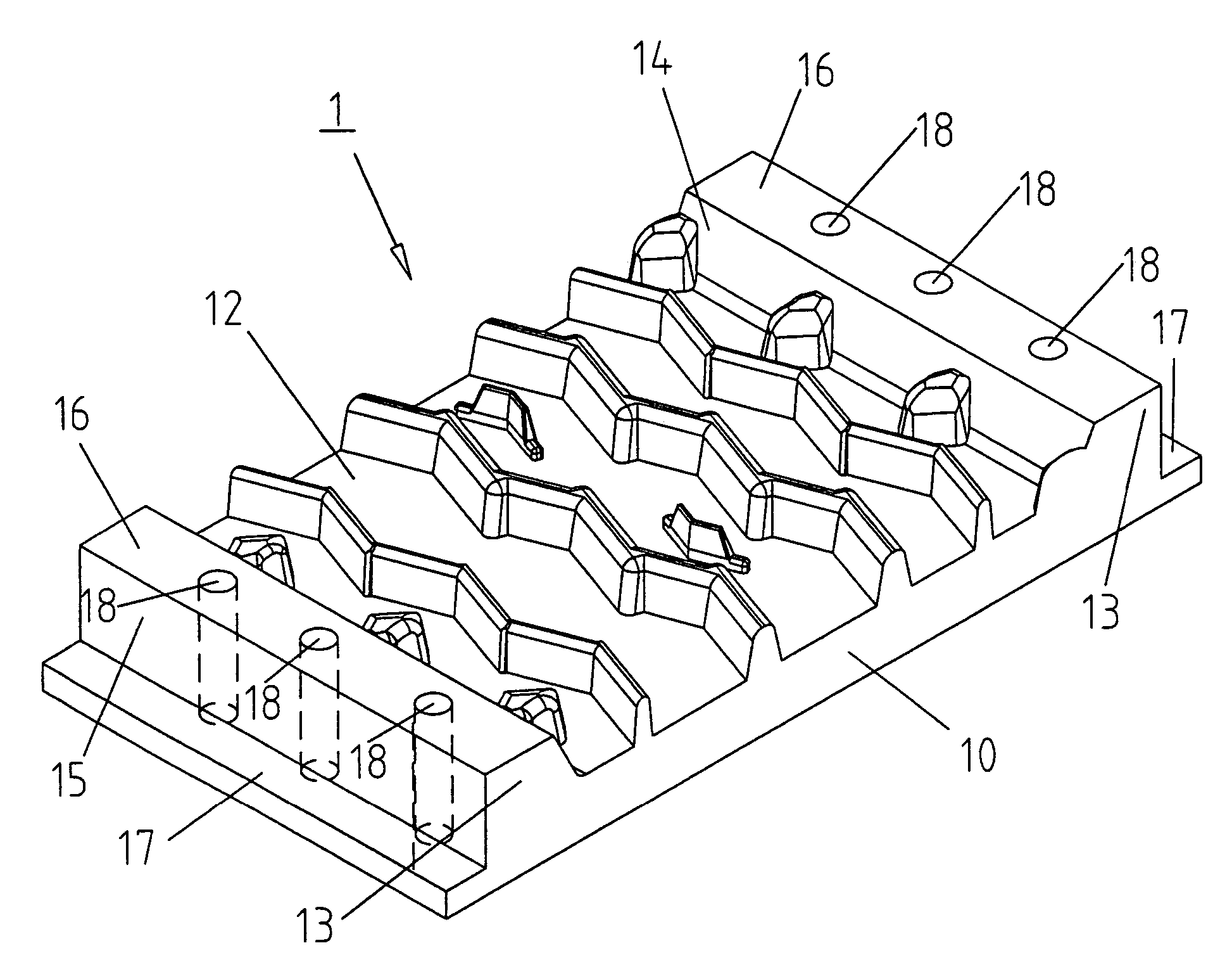
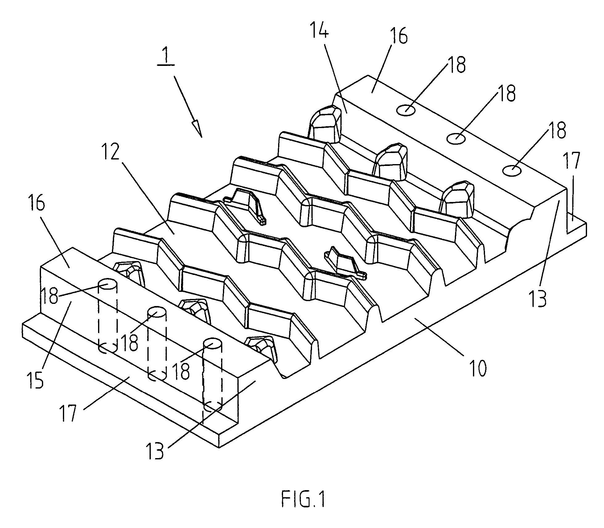
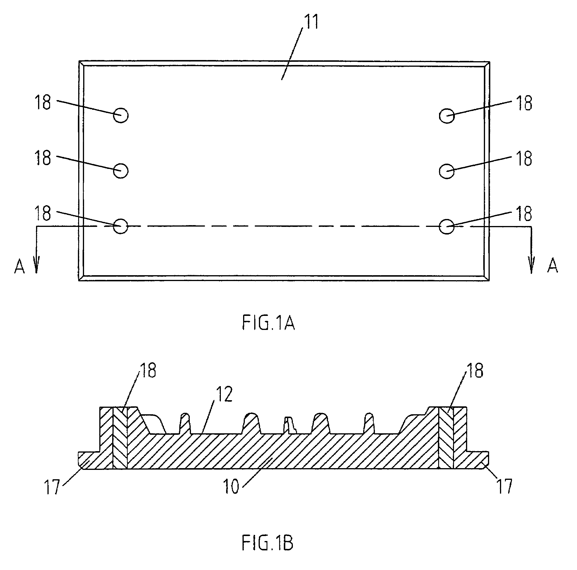
[0016]Shown in FIG. 1 is a mould (1) whereby there is a mould body (10) with a backing and a mould cavity (12). Extend from edges of the mould body (10) and away from the backing are the mould walls (13) each with an inner face (14), an outer face (15) and a contact surface (16). In this example two mould walls (13) are present and are located at two opposite edges of the mould body (10). The mould body (10) and the mould walls (13) in this case form an integral unit. Along the outer face (15) of each of the mould walls (13) and at the lower region is a flange (17) that extends along the whole length of the mould wall. The lower faces of the flanges (17) are at the same level as the mould's backing and together form the backing face (11) of the mould as shown in FIG. 1 and FIG. 1A. The purpose of flanges (17) is for locating and fastening the mould to the moulding machine. The mould is attached to the lower platen of the moulding press whereby backing face (11) of the mould is in co...


PUM

PropertyMeasurementUnit
heightaaaaaaaaaa
densitiesaaaaaaaaaa
dimensional propertiesaaaaaaaaaa

Abstract

The invention relates to a method of strengthening a mould manufactured from aluminium or its alloys. One method of strengthening a mould having mould body and mould walls as an integral unit is to include at least one insert into each of the mould walls. These inserts are of stronger material or materials as compared to the mould material. Each of these inserts is of the same height as that of the mould wall at the position where it is located. Another method uses reinforced walls which are separate units, with the reinforced walls made of a higher strength material or materials than that of the mould body. The reinforced walls are coupled to the mould body either by fasteners or by welding or bonding or by any other suitable means. The invention also relates to moulds including strengthening according to one or more of these methods.

Description

BACKGROUND OF INVENTION[0001]Moulds made from aluminium its alloys are in common use in the rubber moulding industry. These moulds have several advantages. They are easy to cast and machine and moulds with intricate patterns in their cavities can be cast or machined with little difficulties. In addition moulds made from aluminium or its alloys are relatively lighter as they have lower material densities. This facilitates their handling, reducing mould changing times and easing other related activities. Aluminium and its alloy are not expensive raw materials and with the above mentioned benefits moulds made from them are relatively cheaper overall as compared with moulds made from other materials. However aluminium or its alloy as mould material is not without disadvantages. Aluminium and its alloy are in general softer as compared to steel or cast iron. Being softer, deformations of the mould walls and to a lesser extent the mould body and the mould cavity can happen with repeated u...

Claims


Application Information

Patent Timeline
Patent Type & Authority Patents(United States)
IPC IPC(8): B29C33/00B22D19/02B22D19/06B29C33/38B29D30/06
CPCB22D19/02B22D19/06B29C33/38B29D30/0606Y10T29/49988B29K2705/02Y10T29/49826B29C33/00
Inventor LIEW, KHONG FAH
Owner LIEW KHONG FAH
Why Eureka
Try Eureka