Vehicle

a technology for vehicles and vehicles, applied in the field of vehicles, can solve the problems of rider preoccupation, complex operation, and vehicle position, and achieve the effect of good operability

Inactive Publication Date: 2007-04-03
YAMAHA MOTOR CO LTD
View PDF18 Cites 84 Cited by
  • Summary
  • Abstract
  • Description
  • Claims
  • Application Information

AI Technical Summary

Benefits of technology

[0010]In order to overcome the problems described above, preferred embodiments of the present invention provide a vehicle which is capable of detecting a load applied from the rider accurately without any influence from the rider's positions on the vehicle and road conditions, and has good operability.
[0012]According to this preferred embodiment of the present invention, the first frame which is connected with the wheel support is connected with the second frame which is fixed to the load receiver via the connecting member, providing a kind of hinge mechanism for the second frame to pivot with respect to the first frame. The load detector is sandwiched by the first frame and the second frame. Therefore, as the rider rides on the load receiver or transfers his weight thereon, causing the load receiver to apply a load to the wheel, the second frame pivots slightly around the connecting member, and the load is mostly transferred to the load detector without escaping anywhere else. As a result, it is possible to accurately detect the load imparted by the rider, without influence from the riding position of the rider and road conditions. Thus, the rider can ride on the vehicle without worrying about where on the load receiver he should place his feet, and the rider can operate the vehicle naturally and easily as he wants, enjoying the ride itself very much without worrying about or paying attention to the operation. Further, the vehicle does not need many load detectors, which enables a reduction in cost.
[0015]Further preferably, the vehicle further includes an urging member for urging the first frame toward the load receiver. In this case, it becomes possible to prevent the first frame from becoming too far away from the second frame.
[0016]Preferably, the load detector is defined by a strain gauge load cell or a capacitance sensor. In this case, it becomes possible to reduce cost.
[0017]Further, preferably, the load detector includes an elastic member and a position sensor for detecting displacement of the elastic member caused by the load. In this case again, it becomes possible to reduce cost.
[0019]According to this preferred embodiment of the present invention, the second frame receives position regulation so it can move in the load detecting directions, and the load detector is sandwiched by the first frame and the second frame. Therefore, as the rider rides on the load receiver or transfers his weight, causing the load receiver to apply a load to the wheel, the second frame moves, and the load is mostly applied to the load detector without escaping anywhere else. As a result, it is possible to accurately detect the load from the rider, without influence from the riding position of the rider and road conditions. Thus, the rider can ride on the vehicle without worrying about where on the load receiver he should place his feet, and the rider can operate the vehicle naturally and easily as he wants, and enjoy the ride itself very much without worrying about or paying attention to the operation. Further, the vehicle does not need many load detectors, which enables a reduction in cost.

Problems solved by technology

However, according to the technique disclosed in Patent Document 1, the rider's position on the vehicle is limited, operation is complex, and therefore, the rider tends to be preoccupied with the operation during the ride.
Also, if the board is provided with sensors as suggested in Patent Documents 2 and 3, the load applied by the rider is distributed to positions which are located outside of the range of detection by the sensors, making it difficult to detect the load properly to control the vehicle.
If the load is to be detected accurately in such a case, the number of sensors must be increased accordingly, resulting in increased cost.

Method used


Image

  • Vehicle
  • Vehicle
  • Vehicle

Examples


Embodiment Construction

[0032]Hereinafter, preferred embodiments of the present invention will be described with reference to the drawings.

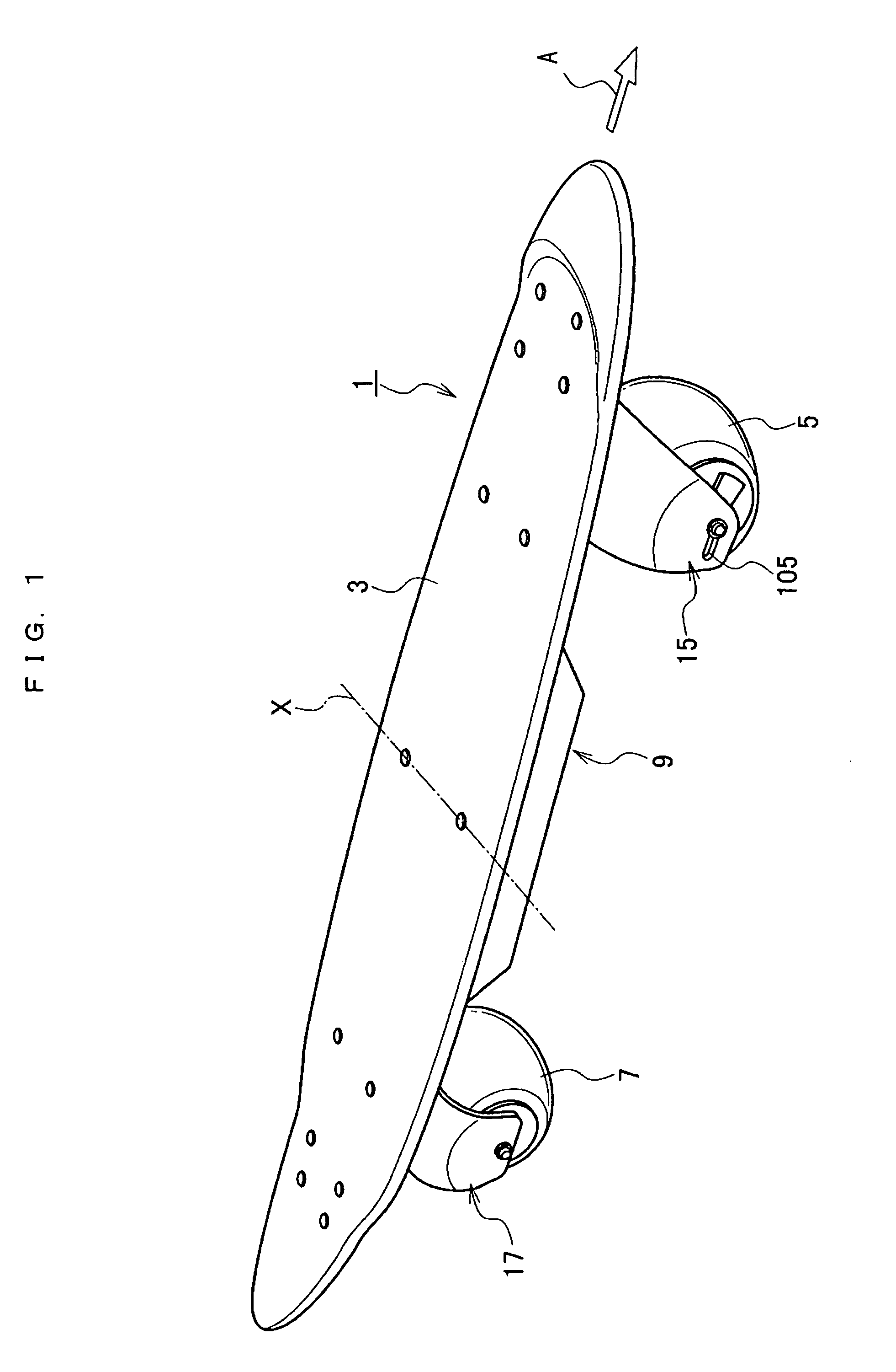
[0033]FIG. 1 shows an electric skateboard 1 as a vehicle according to a preferred embodiment of the present invention.

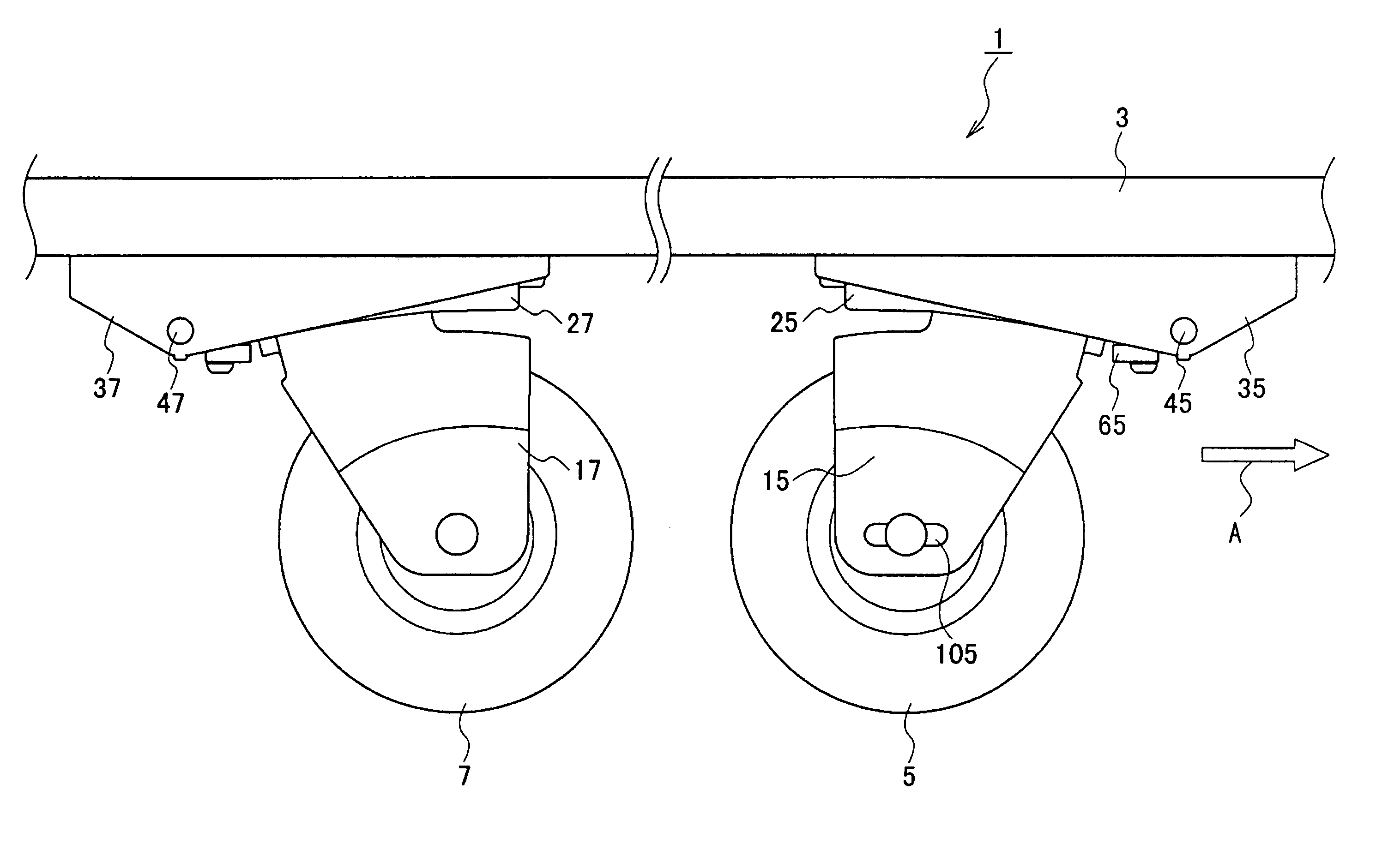
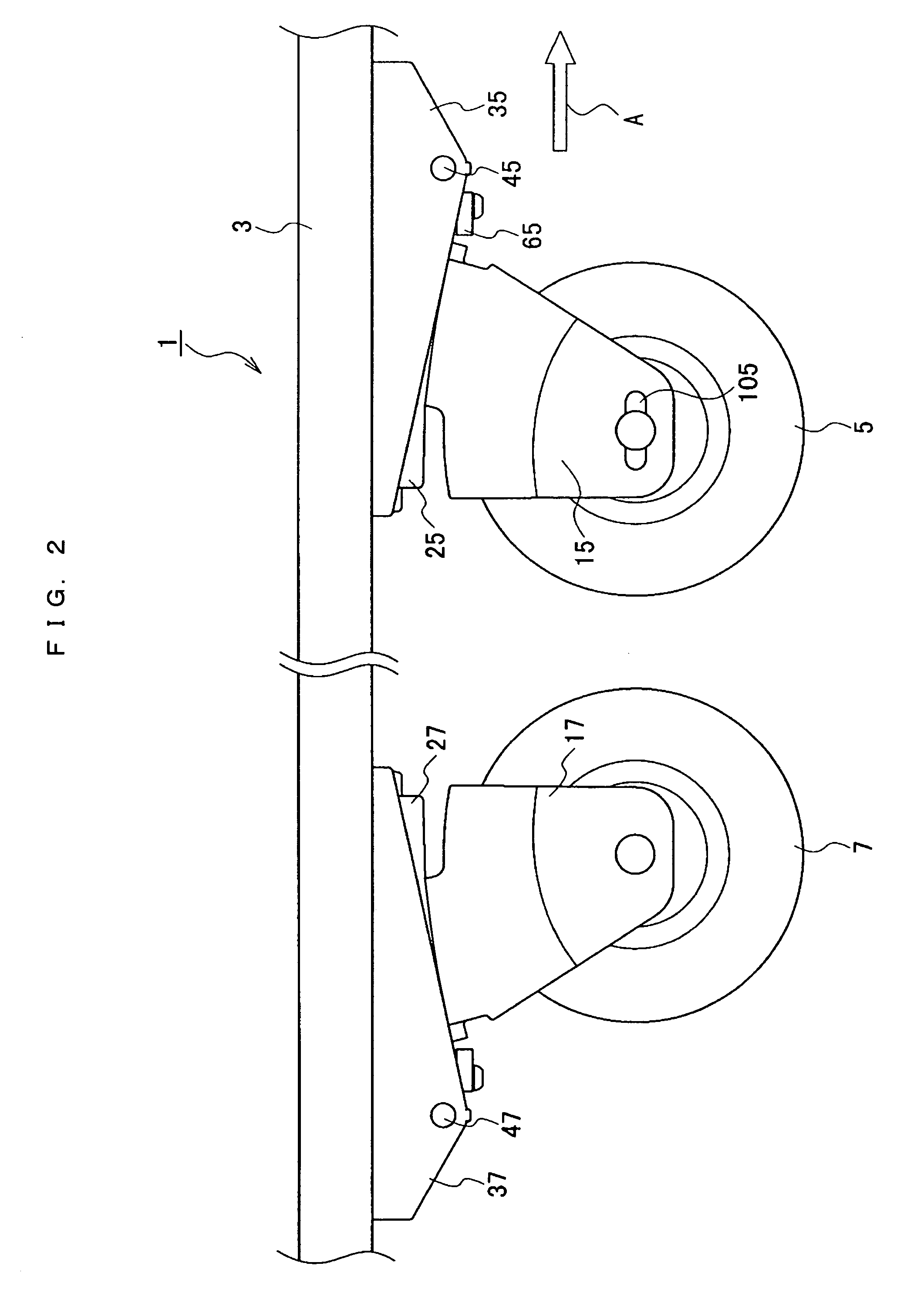
[0034]In the following description, front, rear, right and left directions in the electric skateboard 1 are determined on the basis that a front wheel 5 is on the front side, which means that the direction indicated by Arrow A in FIG. 1 is the forward traveling direction. Upper and lower directions are determined from a driving state of the electric skateboard 1. In other words, upper and lower directions are determined on the basis of a state that the front wheel 5 and a rear wheel 7 are below a board 3.

[0035]Referring to FIG. 1, the electric skateboard 1 includes the board 3 serving as a load receiver which receives the load applied by the rider. The front wheel 5 and the rear wheel 7 are mounted on a lower surface of the board 3, on both longitudinal ...


PUM


Abstract

An electric skateboard is capable of detecting a load applied from a rider accurately without influence from various positions of the rider on the board and without influence from various road conditions. The electric skateboard includes a board arranged to receive a load from the rider, a load detection sensor arranged to detect the load received by the board, a front wheel provided on a lower surface of the board, an arm which rotatably supports the front wheel, a first frame connected with the arm, a second frame fixed to the board, and a shaft connecting the first and second frames. The load detection sensor is sandwiched by the first and second frames. A rear wheel is provided on the lower surface of the board and has a construction that is similar to that of the front wheel.

Description

BACKGROUND OF THE INVENTION[0001]1. Field of the Invention[0002]The present invention relates to a vehicle, and more specifically, the present invention relates to a vehicle such as an electric skateboard which detects a load applied from the rider.[0003]2. Description of the Related Art[0004]Conventionally, electric skateboards, electric wheelchairs, electric carts and so on are known as motor-driven small electric vehicles. These electric vehicles detect a load applied to the vehicle and generate a propelling force based on the load. The vehicles are operated by manually controlling a throttle, a joystick and so on thereby performing operation such as speed and acceleration control, forward / reverse shift, turning signals and steering, etc. (See Patent Document 1, for example).[0005]Also, there have been proposals to provide the board with pressure sensors and strain sensors for controlling driving directions and speed (See Patent Documents 2 and 3, for example)[0006][Patent Docume...

Claims


Application Information

Patent Timeline
Patent Type & Authority Patents(United States)
IPC IPC(8): G10H7/00A63C17/01A63C17/02A63C17/06A63C17/12A63C17/24B60L15/00B62J99/00B62K17/00B62M1/24
CPCA63C17/0033A63C17/01A63C17/016A63C17/12A63C17/223A63C17/24B60L50/52Y02T10/70
Inventor HARA, NOBUO
Owner YAMAHA MOTOR CO LTD
Why Eureka
Try Eureka