Piezoelectric actuator for driving lens

a technology of actuator and driving lens, applied in piezoelectric/electrostrictive/magnetostrictive devices, instruments, mountings, etc., can solve the problems of inaccurate movement of lens barrel, absorbed piezoelectric element by driving member, lens barrel cannot be accurately moved, etc., to achieve accurate movement

Inactive Publication Date: 2007-04-03
FUJI PHOTO OPTICAL CO LTD
View PDF10 Cites 21 Cited by
  • Summary
  • Abstract
  • Description
  • Claims
  • Application Information

AI Technical Summary

Benefits of technology

[0008]The present invention has been made in view of the above described circumstances. An object of the present invention is to provide an actuator capable of stably and accurately moving the driven member.
[0010]According to the first aspect of the present invention, the driving member is formed in a block shape and hence the vibration of the piezoelectric element can be transmitted to the driven member without being attenuated by the driving member, as a result of which the driven member can be accurately moved.
[0011]A second aspect according to the present invention is characterized in that in the first aspect, the driven member is frictionally engaged with both end faces of the driving member in a direction orthogonal to the displacement direction. According to the second aspect, since the driven member is frictionally engaged with both end faces of the driving member, the frictional engagement surface is increased and a large output can be obtained, thereby enabling the driven member to be stably and accurately moved. Specifically, the provision of the frictional engagement surface for both end faces of the driving member prevents the driving force from being non-uniformly transmitted to the driven member, thereby enabling the driven member to be stably and accurately moved.
[0013]In the actuator according to the present invention, since the driving member is formed in a block shape, the vibration of the piezoelectric element is transmitted to the driven member without being attenuated by the driving member, as a result of which the driven member can be accurately moved.

Problems solved by technology

However, since in the actuators disclosed in Japanese Patent No. 2633066 and Japanese Patent Application Laid-open No. 10-232337, driving members (the above described driving rod and engaging member, etc.) are formed in a rod shape or a plate shape, there is a problem that the vibration of the piezoelectric element is absorbed by the driving member so that the lens barrel can not be accurately moved.
Since the high frequency vibration has a large attenuation factor due to the driving member, there is a problem that the response characteristic of the lens barrel is worsened so that the lens barrel cannot be accurately moved.
In the actuators disclosed in Japanese Patent No. 2633066 and Japanese Patent Application Laid-open No. 10-232337, there is also a problem that the frictional force between the driving member and the driven member is insufficient so that the operation of the driven member tends to become unstable.

Method used


Image

  • Piezoelectric actuator for driving lens
  • Piezoelectric actuator for driving lens
  • Piezoelectric actuator for driving lens

Examples


Embodiment Construction

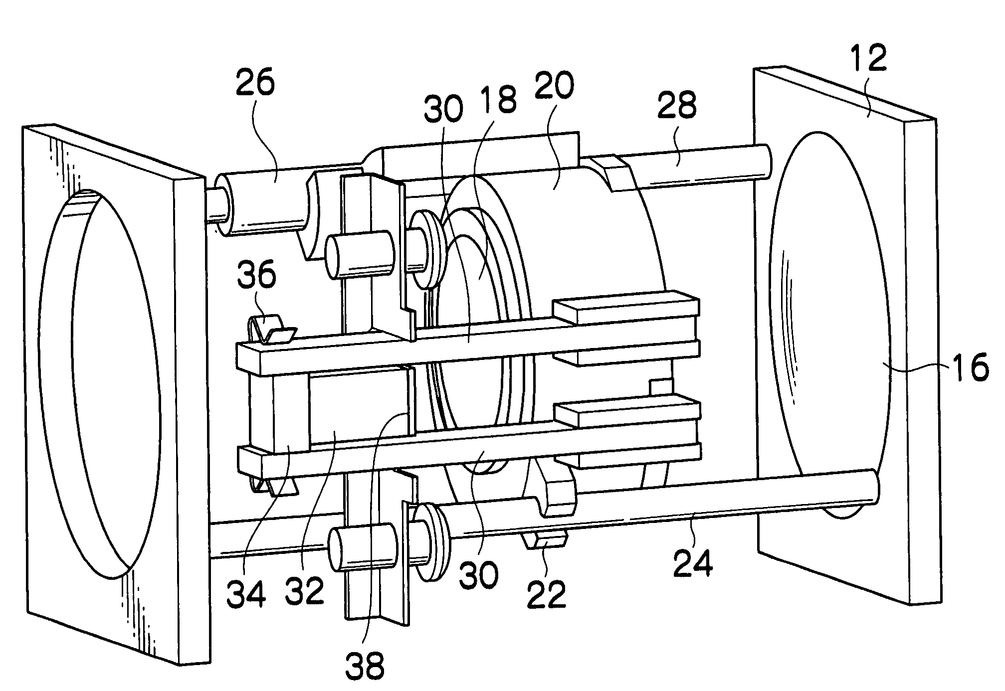
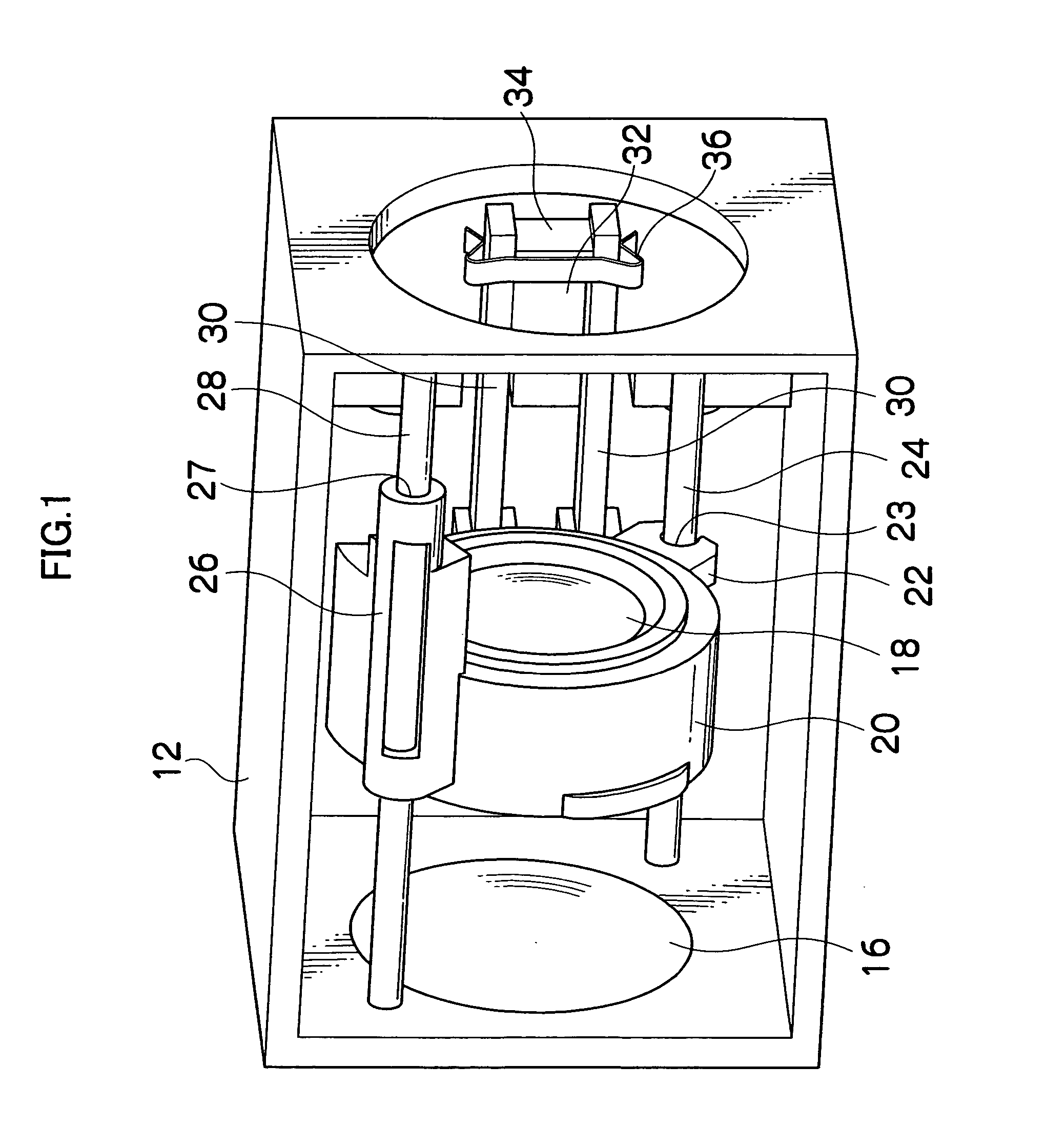
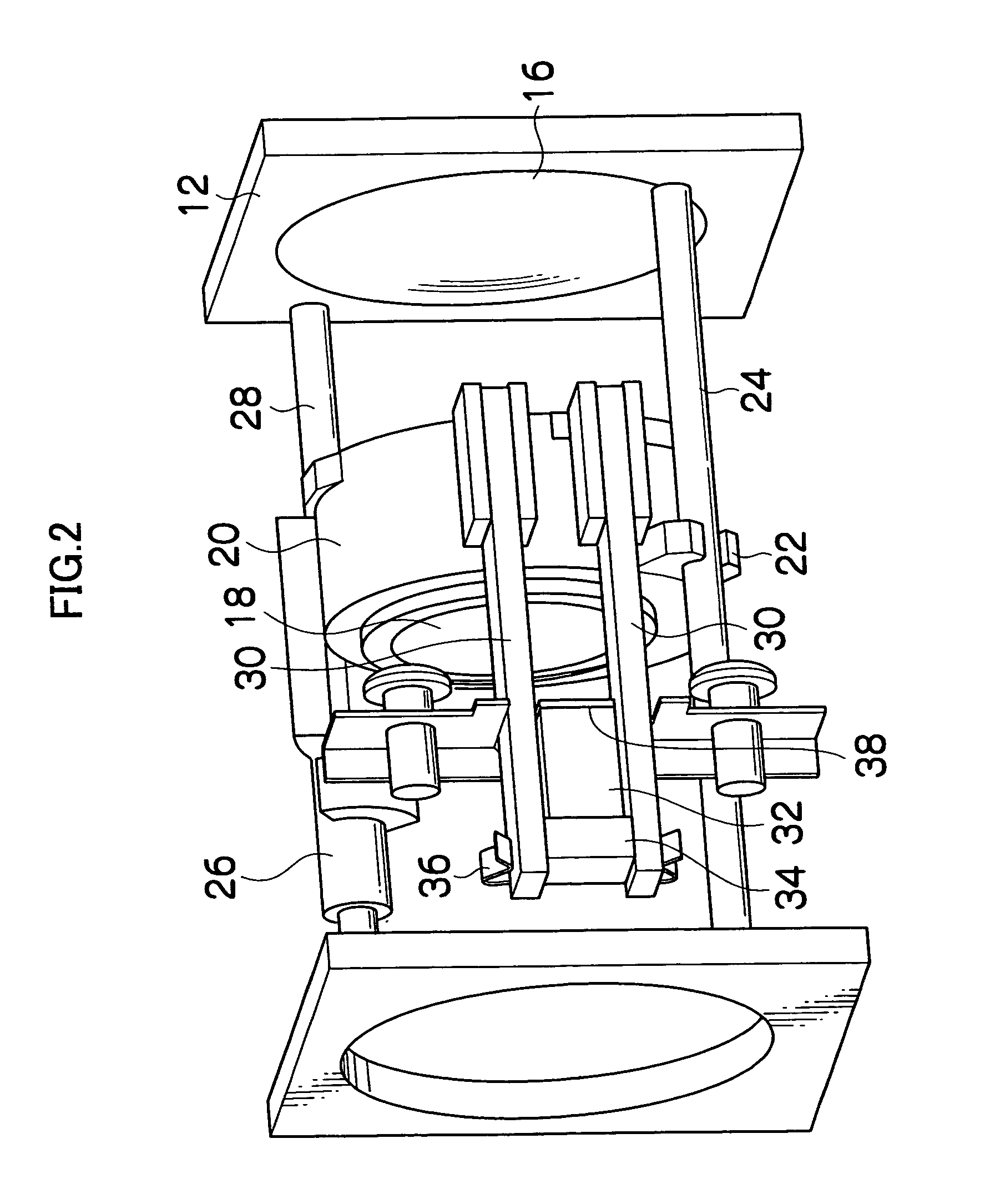
[0020]In the following, preferred embodiments of the actuator according to the present invention are described with reference to the accompanying drawings. FIG. 1 is a perspective view showing a configuration of a lens device to which the actuator of the present invention is applied. The lens device shown in FIG. 1 has a box-shape case 12, to a side face of which a fixed lens 16 is attached. A lens frame 20 holding a moving lens (for example, a zoom lens and a focus lens) 18 is provided in the case 12.

[0021]An engaging portion 22 and a guide portion 26 are formed to project on the external peripheral surface of the lens frame 20. The engaging portion 22 is formed with a U-shaped groove 23 which engages a guide rod 24. The guide portion 26 is formed with a through-hole 27, to which a guide rod 28 is inserted. The guide rods 24, 28 are arranged in a direction of an optical axis, and are fixed to the case 12. Thereby, the lens frame 20 is slidably supported in the direction of the opti...


PUM


Abstract

An actuator of the present invention comprises a piezoelectric element, one end face of the piezoelectric element in a displacement direction being supported by a fixing member, a block shaped driving member attached to the other end face of the piezoelectric element in the displacement direction, and a driven member frictionally engaged with at least one end face of the driving member in a direction orthogonal to the displacement direction, the driven member being extended along the displacement direction.

Description

BACKGROUND OF THE INVENTION[0001]1. Field of the Invention[0002]The present invention relates to an actuator, and more particularly to an actuator which is installed in compact precision instruments such as a digital camera and a portable telephone, and which drives a zoom lens and a focus lens.[0003]2. Related Art[0004]Drives in a lens section of a digital camera, etc. include an actuator using a piezoelectric element. For example, an actuator disclosed in Japanese Patent No. 2633066 has a driving rod which is fixed to an end face of a piezoelectric element, and which slidably supports a lens barrel. A leaf spring is attached to the lens barrel so that a frictional force is applied between the driving rod and the lens barrel by the resilient force of the leaf spring. In addition, approximately sawtooth-shaped driving pulses are applied to the piezoelectric element, which is displaced with different velocities in the expanding direction and in the contracting direction. For example,...

Claims


Application Information

Patent Timeline
Patent Type & Authority Patents(United States)
IPC IPC(8): H01L41/09G02B7/08G02B7/02H02N2/00
CPCG02B7/023G02B7/026H02N2/025
Inventor SASAKI, RYOTAMASUZAWA, TOMONARI
Owner FUJI PHOTO OPTICAL CO LTD
Why Eureka
Try Eureka