
Exposure apparatus

a technology of exposure apparatus and abrasives, which is applied in the direction of recording apparatus, digital computer details, instruments, etc., can solve the problems of low energy utilization efficiency, and achieve the effect of improving the productivity of the exposure apparatus, easy arraying, and easy formation

Inactive Publication Date: 2007-04-03
FUJIFILM CORP +1
View PDF4 Cites 12 Cited by
  • Summary
  • Abstract
  • Description
  • Claims
  • Application Information

AI Technical Summary

Benefits of technology

[0018]Furthermore, when the photosensitive material is exposed, if the light emitting element array in which light emitting elements having the same emission spectrum are arranged is used, all of the light emitting elements should be allowed to emit light in the same luminous intensity according to the color of the lowest spectrum sensitivity of the photosensitive material to be exposed, and thereby, the energy utilization efficiency becomes low. On the other hand, in the case where the photosensitive material is exposed by using the light emitting element array in which plural types of light emitting elements having different emission spectrums, the energy utilization efficiency is improved as compared to the first case.
[0024]As the light emitting elements used in the exposure apparatus of the invention, organic EL elements that are easily arrayed are preferable. A number of organic EL elements are easily formed on a single substrate by using coating and inkjet methods other than vacuum deposition. In the case where the organic EL elements are used as the light emitting elements in the above described exposure apparatus, there are advantages that, as well as the productivity of the exposure apparatus can be improved, the labor of adjusting arrangement positions of the individual light emitting elements is saved, and the arrangement positions can be maintained with high accuracy.
[0025]Note that the exposure apparatus of the invention can be suitably used when the silver halide color photosensitive material is exposed to light. In the case where the silver halide color photosensitive material having low exposure sensitivity of R color is exposed to light, the light emitting elements that emit light in R color become easily degraded, however, by using the exposure apparatus of the invention, the degradation amounts are uniformized among light emitting elements of the respective colors R, G, and B, the streaks of the image are reduced, and thereby, high quality images can be obtained.

Problems solved by technology

Furthermore, when the photosensitive material is exposed, if the light emitting element array in which light emitting elements having the same emission spectrum are arranged is used, all of the light emitting elements should be allowed to emit light in the same luminous intensity according to the color of the lowest spectrum sensitivity of the photosensitive material to be exposed, and thereby, the energy utilization efficiency becomes low.

Method used


Image

  • Exposure apparatus
  • Exposure apparatus
  • Exposure apparatus

Examples


first embodiment

(First Embodiment)

[Construction of Exposure Apparatus]

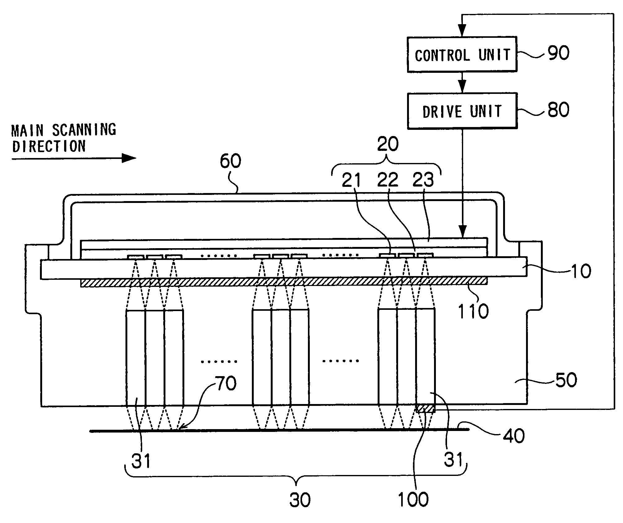
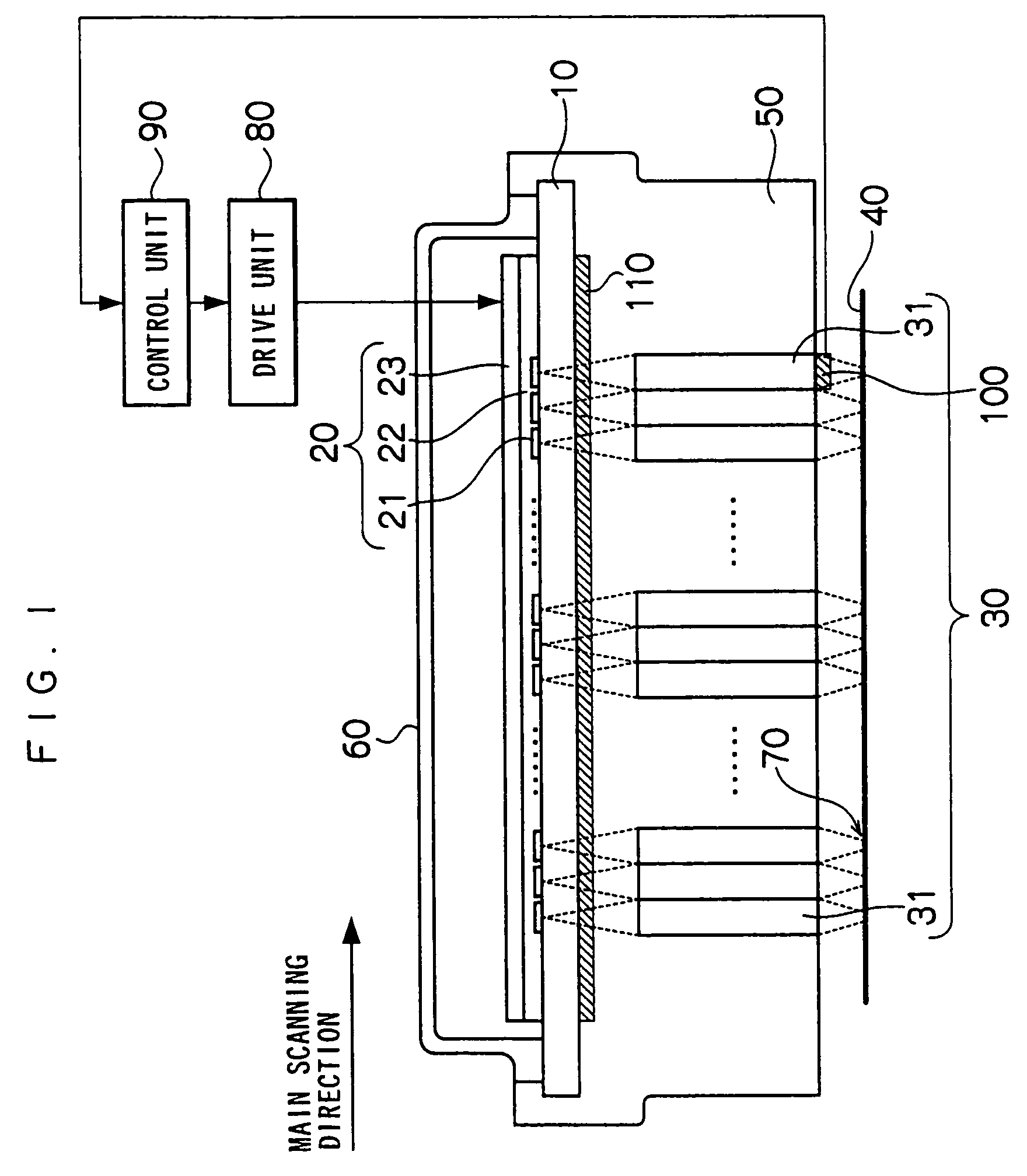
[0053]An exposure apparatus according to an embodiment of the invention comprises a transparent substrate 10, an organic EL array 20 having plural light emitting portions formed on the transparent substrate 10 and emitting light in any color of R, G, and B colors (hereinafter, the respective light emitting portions are referred to as “organic EL elements” for convenience), a filter 110 for selectively transmitting the light from the respective organic EL elements of the organic EL array 20, a Selfoc lens array 30 (hereinafter, referred to as “SLA”; trade name) for concentrating the light transmitted through the filter 110 and irradiating the photosensitive material 40, and a supporting body 50 for supporting the transparent substrate 10 and the SLA 30, as shown in FIG. 1.

[0054]The organic EL array 20 is formed by sequentially laminating a transparent electrode 21 as an anode, an organic compound layer22 including a light emitting...

second embodiment

(Second Embodiment)

[0095]Since an exposure apparatus according to a second embodiment has the same construction with the exposure apparatus according to the first embodiment, except that the filter is not provided on the rear surface of the transparent substrate 10, as shown in FIG. 8, and the arrangement and the luminous intensity of the organic EL elements are different, the same components are assigned with the same signs and the description thereof will be omitted.

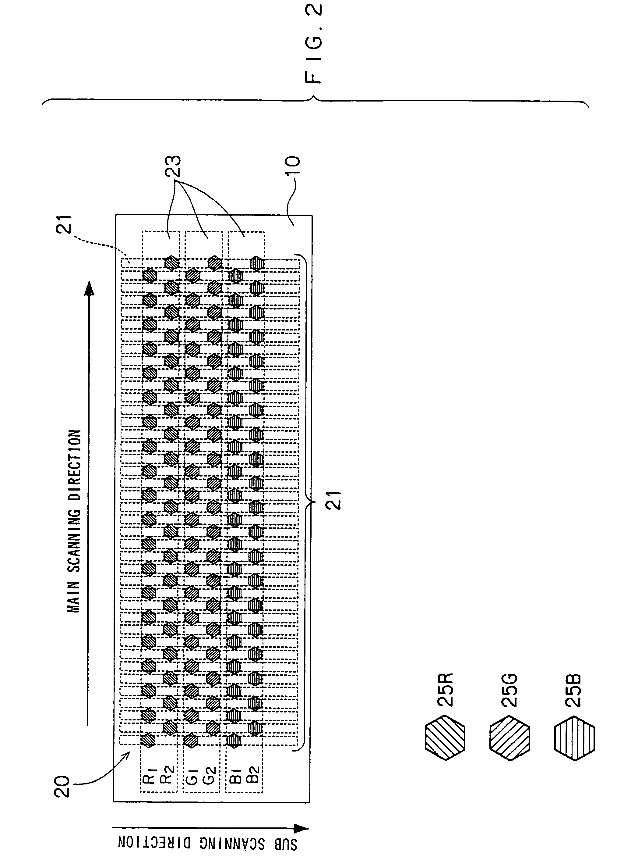
[0096]In the first embodiment, different luminous intensities are set for the respective colors so that the degradation rates may be substantially the same among the organic EL elements of three colors R, G, and B, and the transmittances of the respective color filters are adjusted so that the desired exposure spectral intensity may be obtained. However, in the second embodiment, by setting different luminous intensities for the respective colors so that the degradation rates may be substantially the same among organic...


PUM


Abstract

Provided is an exposure apparatus capable of suppressing deviation of color balance by simple apparatus construction. Further, provided is an exposure apparatus capable of performing exposure with high energy utilization efficiency. The luminous intensity and emission time of each organic EL element of an organic EL array are set according to inputted image data, and the set values of luminous intensity and emission time are stored in a RAM. The organic EL elements of respective colors have different luminous intensities set so that degradation rates are substantially the same among three colors of R, G, and B. Next, control signals are generated based on the set values of the luminous intensities and emission times, and the generated control signals are outputted.

Description

CROSS-REFERENCE TO RELATED APPLICATION[0001]This application claims priority under 35 USC 119 from Japanese Patent Application No. 2002-337771, the disclosure of which is incorporated by reference herein.BACKGROUND OF THE INVENTION[0002]1. Field of the Invention[0003]The present invention relates to an exposure apparatus, specifically, to an exposure apparatus for exposing a photosensitive material to light emitted from an array of light emitting elements.[0004]2. Description of the Related Art[0005]An organic EL (electroluminescent) element using a fluorescent organic material as a light emitting layer has the advantages that it can be manufactured more easily than other light emitting elements, it can constitute a thin and lightweight light emitting device, etc., and thereby, research and development as a thin display element has been conventionally promoted. Recently, since an organic EL element achieving high performance also in luminous brightness, luminous efficiency, and dura...

Claims


Application Information

Patent Timeline
Patent Type & Authority Patents(United States)
IPC IPC(8): G09G3/30B41J2/44B41J2/45B41J2/455G06K15/12H01L51/50H05B33/14
CPCG06K15/129B41J2/451B41J2/455G06K2215/0085
Inventor HYUGA, HIROAKI
Owner FUJIFILM CORP
Learn More