Punch capable of punching an object at four directions

a technology of punching and object, applied in the field of punching, can solve the problems of not being able to simultaneously punch or emboss the sheet members in different patterns at four directions, and achieve the effect of convenient use and improved structur

Inactive Publication Date: 2007-04-10
DN CRAFT
View PDF16 Cites 25 Cited by
  • Summary
  • Abstract
  • Description
  • Claims
  • Application Information

AI Technical Summary

Benefits of technology

[0007]The present invention is designed to solve the problems of the prior art, and therefore it is an object of the present invention to provide a punch having a fundamentally improved structure so that sheet members may be supplied at four directions of a jig. According to the present invention, the jig is very convenient to use since punching and / or embossing work may be conducted at four directions, and it is possible to form various kinds of punching patterns by one punch.

Problems solved by technology

However, in the configuration of the above jig, a sheet member may be supplied at most at three directions, but it is impossible to put sheet members and then simultaneously punch or emboss the sheet members in different patterns at four directions.

Method used


Image

  • Punch capable of punching an object at four directions
  • Punch capable of punching an object at four directions
  • Punch capable of punching an object at four directions

Examples


Embodiment Construction

[0021]Hereinafter, the present invention will be described in more detail referring to the drawings.

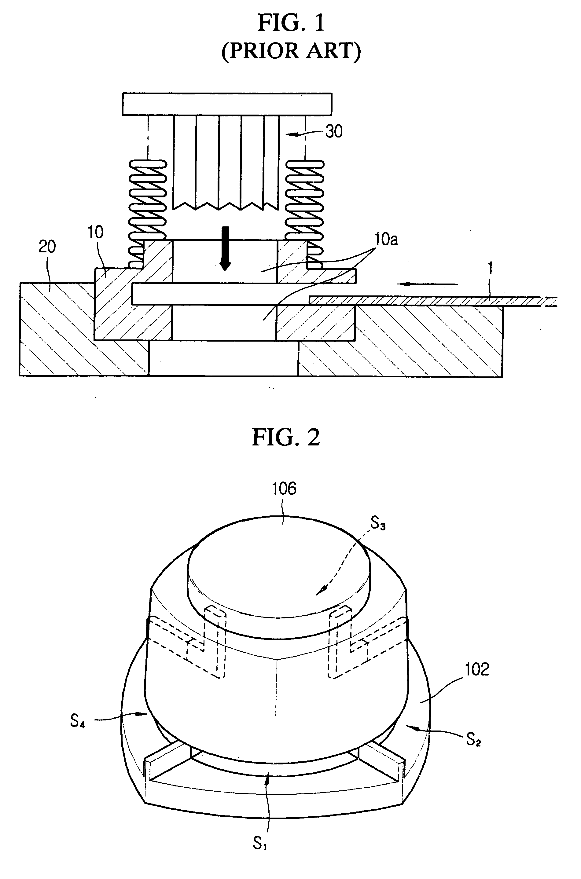
[0022]FIG. 2 shows an appearance of a punch according to a preferred embodiment of the present invention. As shown in FIG. 2, four sheet member supply regions S1, S2, S3 and S4 orthogonal to each other are prepared on a base 102, and a button member 106 is mounted thereto to be movable up and down. According to the punch as mentioned above, various kinds of patterns may be conveniently formed in a sheet member by putting the sheet member in any of the sheet member supply regions S1, S2, S3 and S4 on the base 102, and then pressing the button member 106 downward.

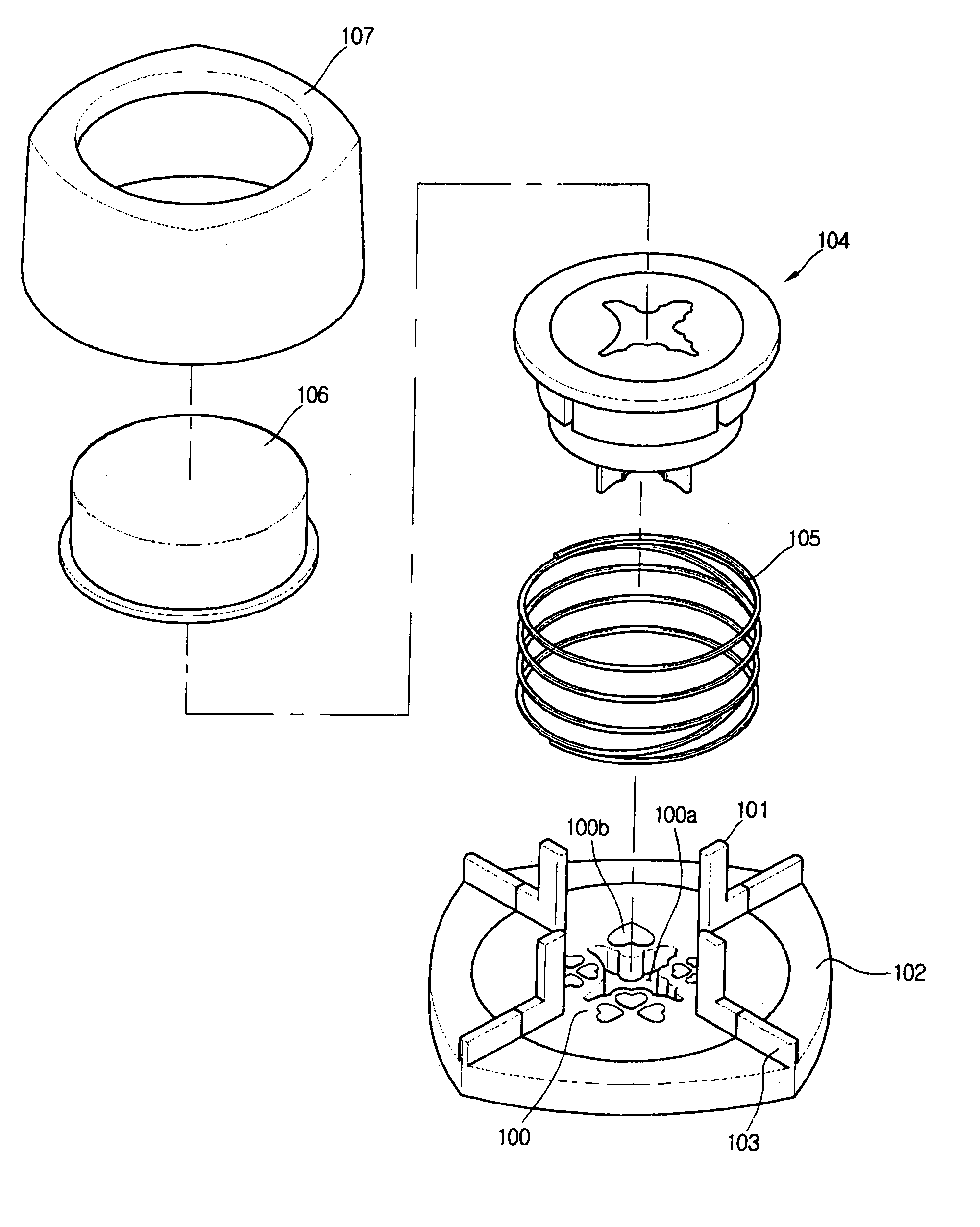
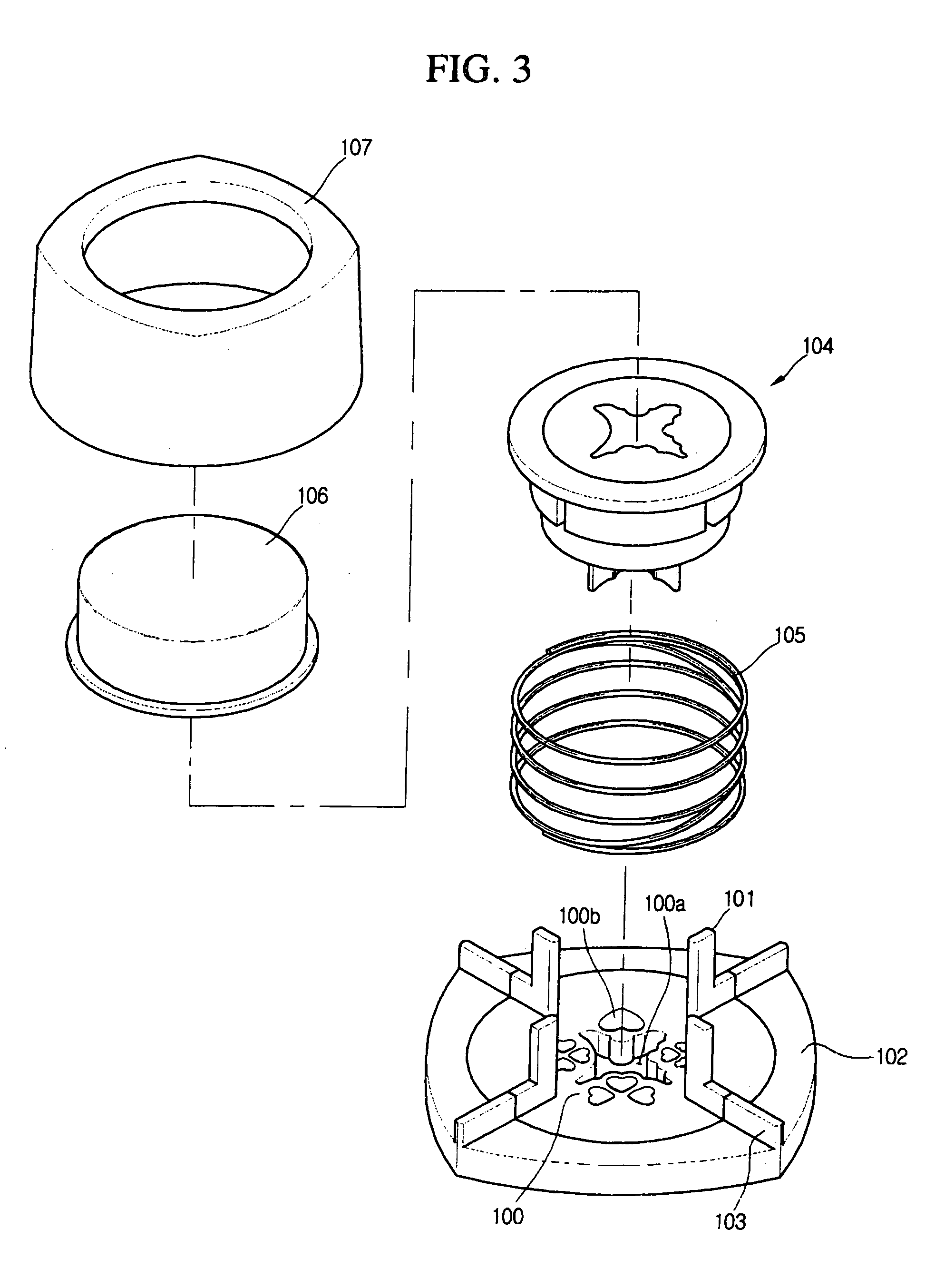
[0023]FIG. 3 shows the punch according to a preferred embodiment of the present invention in detail.

[0024]Referring to FIG. 3, the punch of the present invention includes a jig 100 having a pattern hole 100a, a base 102 for supporting the jig 100 and having guide units 103 at four positions, a punching member 104 installed to b...


PUM

PropertyMeasurementUnit
U' shapeaaaaaaaaaa
structureaaaaaaaaaa
elasticaaaaaaaaaa

Abstract

A punch includes a jig having four punching regions, each punching region having a pattern hole and a concave embossment; guide columns extended upward from a border of the punching regions on the jig; a base for fixing the jig; a punching member punching and embossing the rectangular corner of a sheet member with vertically moving against the jig by guidance of the guide columns; and an elastic body to elastically bias the punching member upward.

Description

BACKGROUND OF THE INVENTION[0001]1. Field of the Invention[0002]The present invention relates to a punch for punching a sheet member in a predetermined pattern, and more particularly to a punch capable of allowing easy use and having various kinds of punching patterns since a sheet member may be supplied at four directions when a user punches a rectangular corner of the sheet member such as a card, a letter paper, a picture, a board or a paper.[0003]2. Description of the Related Art[0004]A punch generally includes a jig 10 having a hole 10a of a predetermined pattern, a base 20 for supporting the jig 10 below it, and a cutting member 30 having a sharp blade sliding through the hole 10a of the jig 10, as schematically shown in FIG. 1. The punch performs punching a specific portion of a sheet member 1 according to the pattern of the hole 10a of the jig 10.[0005]In a general punch, a gap is necessarily prepared to the jig 10 for the insertion of a sheet member. To form the gap, the jig...

Claims


Application Information

Patent Timeline
Patent Type & Authority Patents(United States)
IPC IPC(8): B26F1/12B31F1/07B26D3/14B26F1/14B26D3/10
CPCB26D3/10B26F1/36Y10S83/917Y10T83/7593Y10T83/8785Y10T83/8853Y10T83/8855Y10T83/9425Y10T83/9428Y10T83/9444B26F1/38
Inventor OH, WAN-YOUNG
Owner DN CRAFT
Why Eureka
Try Eureka