Supercharge Your Innovation With Domain-Expert AI Agents!

Vehicular power unit

a power unit and crankshaft technology, applied in the field of vehicles, can solve the problems of the crankshaft cover and the chain cover overlapping, and achieve the effect of reducing the power unit, preventing the weight of the generator from increasing, and effectively suppressing the rotational fluctuation of the cranksha

Inactive Publication Date: 2007-04-10
HONDA R&D
View PDF12 Cites 10 Cited by
  • Summary
  • Abstract
  • Description
  • Claims
  • Application Information

AI Technical Summary

Benefits of technology

[0009]The invention is made in view of such a situation and one object is to provide a vehicular power unit that can be made compact in a direction along an axis of a crankshaft. Another object of the invention is to downsize the power unit by disposing a crankshaft and an output shaft parallel with each other at an interval in the arranging direction. Additional objects of the invention include effectively suppressing the rotational fluctuation of a crankshaft with a generator while preventing the weight of the generator from increasing and increasing the versatility of a traveling guide for guiding an endless transmission belt.
[0010]According to a first aspect of the present invention, a vehicular power unit provided with an engine in which a crankshaft is rotatably supported by a crankcase, and a transmission housed in the crankcase for shifting power transmitted from the crankshaft. A drive-side transmission sprocket wheel, onto which an endless transmission belt for transmitting power to a driving wheel is wound is provided to the end protruded from one side of the crankcase of an output shaft of the transmission. A water pump, arranged between the crankshaft and the output shaft, is arranged on one side of the crankcase. Further, the water pump is arranged inside the drive-side transmission sprocket wheel in a direction along the axis of the output shaft. Since the water pump is arranged inside the drive-side transmission sprocket wheel, the water pump is not protruded outside from the drive-side transmission sprocket wheel. Further, the power unit can be made compact in the direction along the axis of the crankshaft, and the concentration of mass can contribute to the enhancement of the driving performance of the vehicle.
[0011]According to a second aspect of the present invention, a cover at least a part of which is overlapped with the water pump from the outside when the cover is viewed from a direction along the axis of the output shaft is attached to the crankcase, covering the drive-side transmission sprocket wheel. Since the output shaft of the transmission and the water pump can be closely arranged and accessories can be concentrated three-dimensionally, mass can be concentrated more.

Problems solved by technology

Further, a generator attached to a crankshaft functions as a rotary inertial mass to suppress the rotational fluctuation of the crankshaft and, when it is attempted to increase the diameter of the rotor of the generator in order to increase the rotary inertial mass without increasing the weight of the generator, a crankcase cover and a chain cover interfere with each other.

Method used


Image

  • Vehicular power unit
  • Vehicular power unit
  • Vehicular power unit

Examples


Embodiment Construction

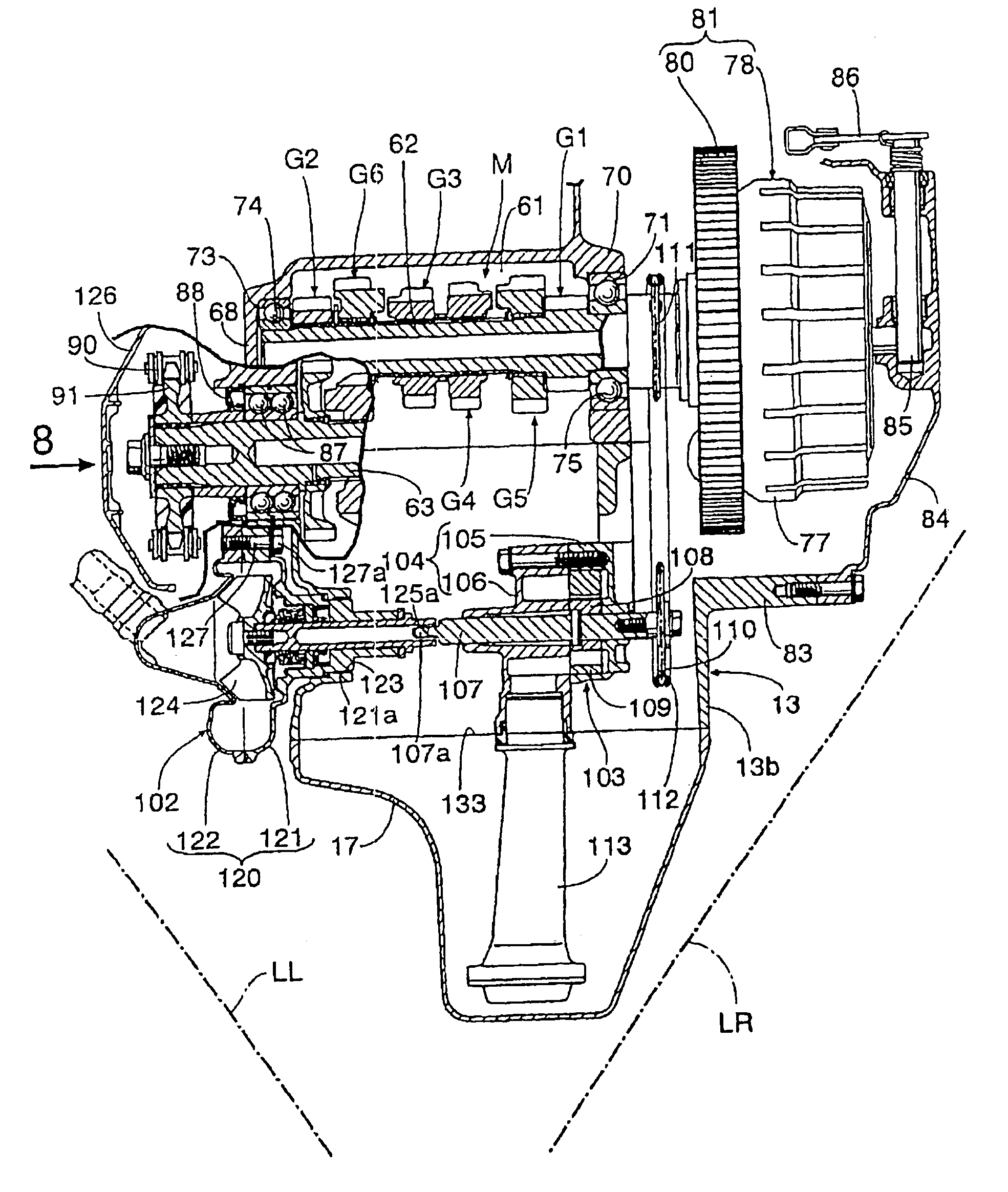
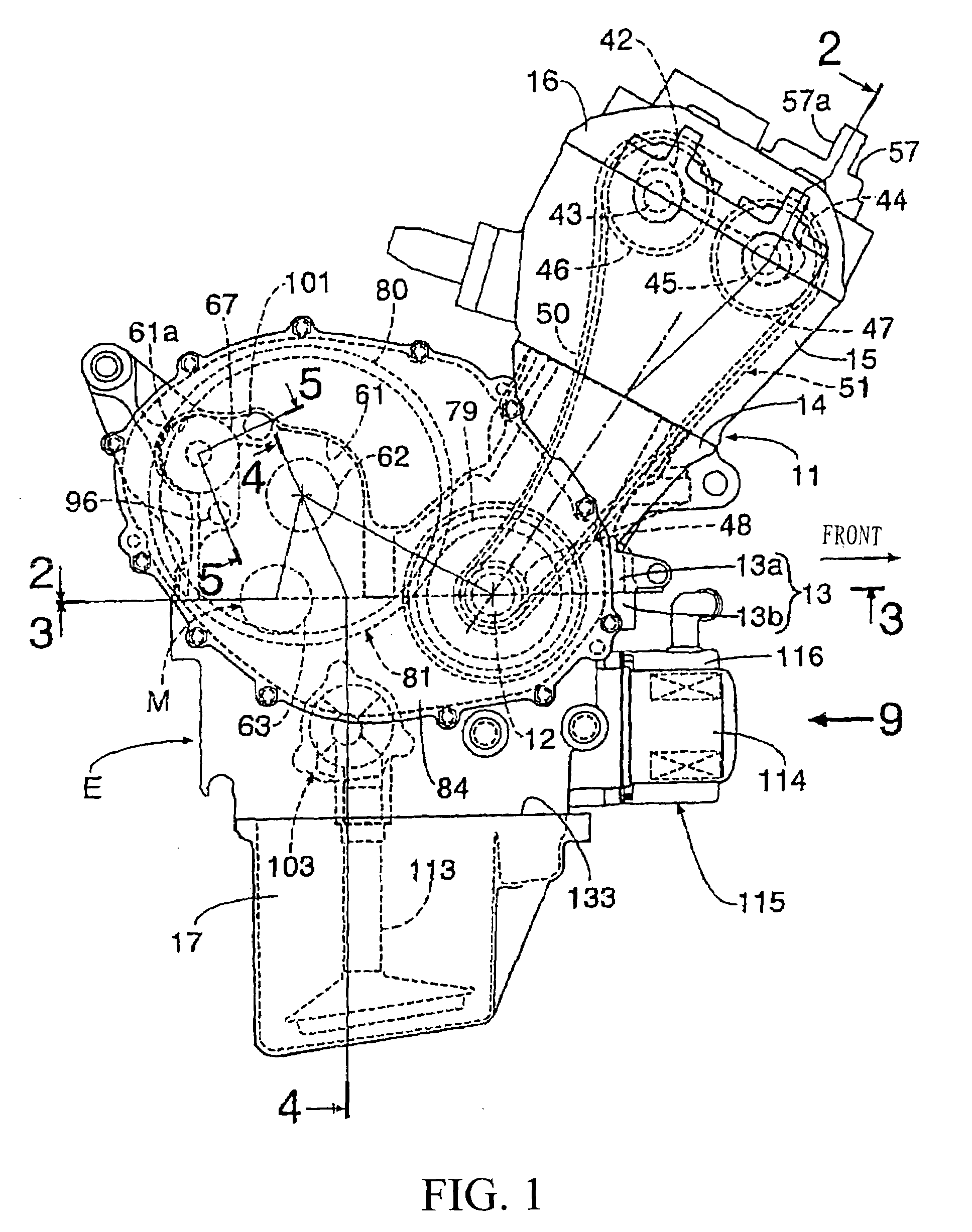
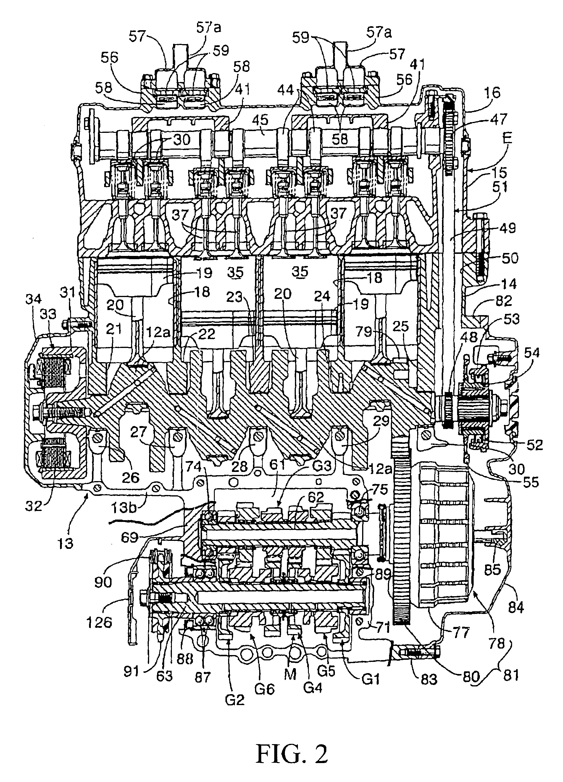
[0044]FIGS. 1 to 9 show one embodiment of the invention. First, as shown in FIG. 1, this power unit is mounted in a vehicle, for example, a motorcycle, and is provided with an in-line 4-cylinder water-cooled engine E for example and a constant-mesh type gear transmission M that shifts the output of the engine E.

[0045]A body 11 of the engine E is provided with: a crankcase 13 for rotatably supporting a crankshaft 12 having an axis extended in a lateral direction of the motorcycle; a cylinder block 14 coupled to the crankcase 13 on the front side in a traveling direction of the motorcycle; a cylinder head 15 coupled to the upper end of the cylinder block 14; and a head cover 16 coupled to the upper end of the cylinder head 15. An oil pan 17 is coupled to a lower part of the crankcase 13.

[0046]The crankcase 13 is formed by mutually connecting an upper case 13a and a lower case 13b respectively cast and the crankshaft 12 is rotatably supported between the upper case 13a and the lower ca...


PUM


Abstract

A vehicular power unit including a drive-side transmission sprocket wheel provided on an end of an output shaft that protrudes from one side of a crankcase, an endless transmission belt for transmitting power to a driving wheel wound the sprocket wheel. The endless transmission belt transmits power from the crankshaft to a transmission housed in the crankcase. A water pump is arranged on the same side of the crankcase in a position between the crankshaft and the output shaft. Further, the water pump is disposed inside the drive-side transmission sprocket wheel in a direction along the axis of an output shaft. This configuration enables the vehicular power unit to be formed in a compact size in a direction along an axis of a crankshaft.

Description

CROSS-REFERENCE TO RELATED APPLICATION[0001]The present application claims priority under 35 U.S.C. §119 to Japanese Patent Application No. 2005-287125, filed Sep. 30, 2005, Japanese Patent Application No. 2005-092402, filed Mar. 28, 2005, and Japanese Patent Application No. 2005-285799, filed Sep. 30, 2005, the entire contents of which are hereby incorporated by reference.BACKGROUND OF THE INVENTION [0002]1. Field of the Invention[0003]The present invention relates to a vehicular power unit provided with an engine in which a crankshaft is rotatably supported by a crankcase and a transmission housed in the crankcase for shifting power transmitted from the crankshaft. A drive-side transmission sprocket wheel, onto which an endless transmission belt for transmitting power to a driving wheel is wound, is provided on an end of an output shaft of the transmission protruding from one side of the crankcase. In addition, a water pump is arranged on the same side of the crankcase in a positi...

Claims


Application Information

Patent Timeline
Patent Type & Authority Patents(United States)
IPC IPC(8): F01P5/10F02B61/04F02F1/10
CPCF02B61/02F02B63/02F01P5/12F02B63/04
Inventor TAWARADA, YUICHISHIOZAKI, EIKOKAWAKUBO, HIROYUKINAKAI, KAZUYUKI
Owner HONDA R&D
Features
  • R&D
  • Intellectual Property
  • Life Sciences
  • Materials
  • Tech Scout
  • Unparalleled Data Quality
  • Higher Quality Content
  • 60% Fewer Hallucinations
Learn More