Elevator installation having a virtual protection area at the bottom and/or the top of the elevator shaft, and method for controlling the same

a technology for elevators and protection areas, which is applied in the direction of elevators, transportation and packaging, etc., can solve the problems of increased construction costs and aesthetics disadvantages of buildings, and achieve the effect of small dead times

Active Publication Date: 2007-04-10
INVENTIO AG
View PDF9 Cites 29 Cited by
  • Summary
  • Abstract
  • Description
  • Claims
  • Application Information

AI Technical Summary

Benefits of technology

[0025]The elevator installation according to the present invention is distinguished by smaller

Problems solved by technology

Nevertheless, even here a protective space has to be planned in at the lower and/or upper shaft end due to regulations, which can be disadvantageous for the aesthetics of the building.
Apart from the aesthetic and constructional problems which result from the neces

Method used


Image

  • Elevator installation having a virtual protection area at the bottom and/or the top of the elevator shaft, and method for controlling the same
  • Elevator installation having a virtual protection area at the bottom and/or the top of the elevator shaft, and method for controlling the same
  • Elevator installation having a virtual protection area at the bottom and/or the top of the elevator shaft, and method for controlling the same

Examples


Embodiment Construction

[0035]The present invention is substantially independent of the form of elevator layout and of the form of drive that is used. For these reasons in the following the cables or rails, counterweights and other elements are regarded as a constituent of the drive unit and are individually described or discussed only so far as necessary. In addition, the control is considered to be a constituent of the drive unit.

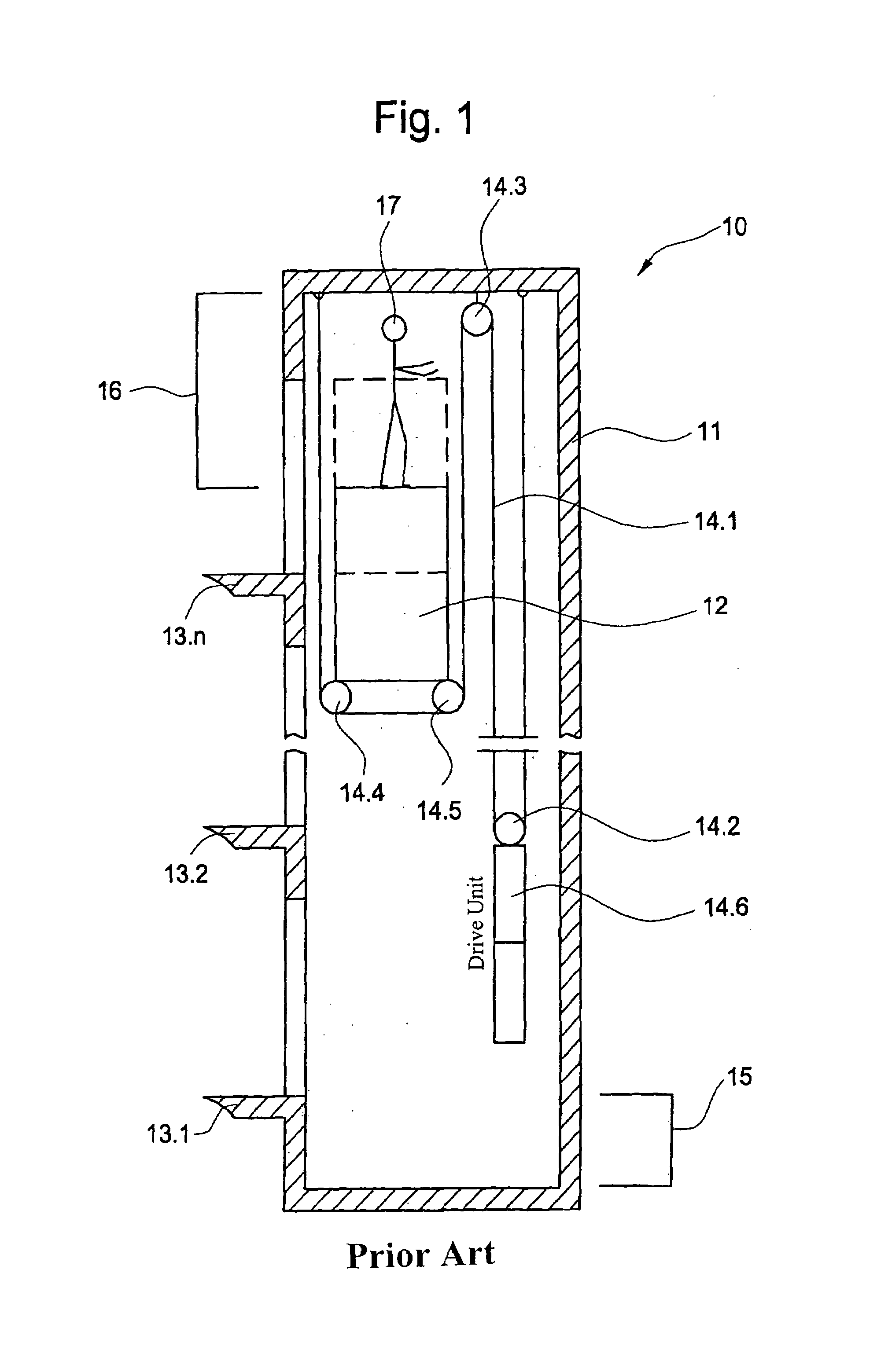
[0036]A conventional elevator installation 10 is shown in FIG. 1. The illustrated installation 10 comprises a shaft 11 with a cage 12, which can travel to different floor levels 13.1 to 13.n. The drive unit comprises the cable 14.1, the rollers or suspensions 14.2 to 14.6, the drive motor (not illustrated) and the control unit for control of the drive motor (not illustrated). A shaft pit 15, which serves as a lower protective space, is disposed at the lower shaft end in accordance with regulations. A protective space 16 is provided at the upper shaft end so that a person 17 loca...


PUM


Abstract

An elevator installation with an elevator case, an elevator shaft, and a drive unit. The elevator cage is installed in the elevator shaft to be movable and is controllable by the drive unit so that the elevator cage can be stopped in different positions in the elevator shaft. The elevator shaft is equipped with a detecting device which detects whether a person is standing in a critical zone in the elevator shaft or is about to go into this. The detecting device is connected with the drive unit so that the elevator installation can be transferred to a special mode of operation in case a person is standing in the critical zone or is about to go into this. The drive unit includes special control equipment which in the special mode of operation stops the elevator cage before it moves into the critical zone. In that case the detecting device and the special control equipment are designed to be operationally safe in order to prevent movement of the elevator cage into the critical zone. The special control equipment enables, in the special mode of operation, an undisturbed operation of the elevator cage in a zone outside the critical zone.

Description

PRIORITY CLAIM[0001]This is a U.S. national stage of application No. PCT / CH02 / 00363, filed on Jul. 3, 2002. Priority is claimed on that application and on the following application:[0002]Country: EUROPE, Application No.: 01810673.2, Filed: Jul. 9, 2001.BACKGROUND OF THE INVENTION[0003]An elevator installation comprises, in a conventional manner, an elevator cage, an elevator shaft in which the elevator cage moves and a drive unit for moving the elevator cage.[0004]For reasons of safety, present-day elevator installations are designed so that a protective space in the form of a shaft pit is located at the shaft base in order to ensure that maintenance personnel in the shaft are not placed at risk when the elevator cage travels into the lowermost position in the shaft. Typically, an elevator installation is also designed so that a protective space is located at the upper end of the shaft—called shaft head—so that maintenance personnel undertaking maintenance on the roof of the cage ar...

Claims


Application Information

Patent Timeline
IPC IPC(8): B66B1/26B66B5/00
CPCB66B5/0043
Inventor DEPLAZES, ROMEOANGST, PHILIPP
Owner INVENTIO AG
Why Eureka
Try Eureka