Contoured CMP pad dresser and associated methods

a technology of chemical mechanical polishing and dressing pad, which is applied in the direction of grinding device, manufacturing tool, abrasive surface conditioning device, etc., can solve the problems of significantly reducing the overall polishing performance of the pad, the pad is less able to hold abrasive particles, and the top of the pad, so as to increase the work load, optimize the work load, and increase the penetration

Inactive Publication Date: 2007-04-10
KINIK
View PDF91 Cites 79 Cited by
  • Summary
  • Abstract
  • Description
  • Claims
  • Application Information

AI Technical Summary

Benefits of technology

[0012]Accordingly, in one aspect, the present invention provides methods and CMP pad dresser configurations for increasing the work load on centrally located superabrasive particles in a CMP pad dresser during dressing of a CMP pad. In one such method, a CMP pad dresser is provided which has a plurality of superabrasive particles each coupled to a substrate member and held at specific locations in accordance with a predetermined pattern. The superabrasive particles can be configured in a pattern that reduces the penetration of peripherally located particles into the CMP pad and increases penetration of centrally located particles into the CMP pad, thus optimizing the work load placed on the centrally located superabrasive particles. Generally, the particles are of a super hard substance such as diamond, or cubic boron nitride (cBN), in either the single crystal or polycrystalline form.
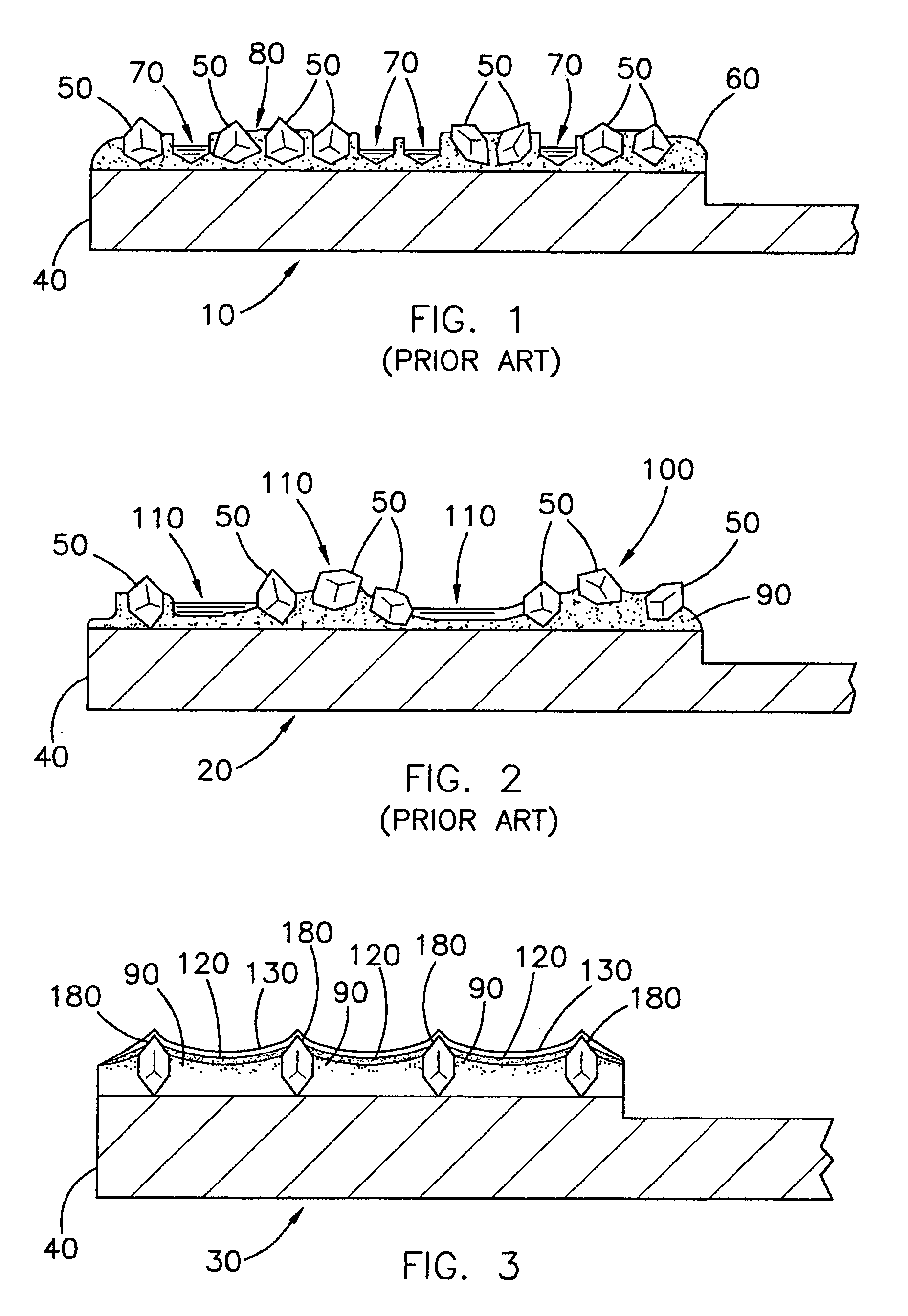
[0014]In yet another embodiment of the present invention, a method for increasing the work load on the centrally located particles may include providing a CMP pad dresser having a plurality of superabrasive particles coupled to a substrate in a pattern that places the peripherally located superabrasive particles at a higher density than the centrally located particles. It has been found that particles clustered in a higher density are unable to penetrate into the pad as deeply as those spaced farther apart from one another. Therefore, by varying densities of particles on the substrate work load can be transferred from one area to another.
[0015]In still another embodiment of the present invention a method of increasing the work load on centrally located particles may be achieved by orienting the centrally located particles with an attitude that causes higher particle penetration into the CMP pad than penetration provided by an attitude of the peripherally located particles. In one aspect, the attitude of the centrally located particles can present an apex at the working end thereof, and the attitude of the peripherally located particles can present either a face or an edge at the working end thereof. In another aspect, the attitude of the centrally located particles can present an edge at the working end thereof, and the attitude of the peripherally located particles can present a face at the working end thereof. In yet another aspect, when the attitude of the centrally located particles presents an apex at the working end thereof, the attitude of the peripherally located particles can present a face at the working end thereof, and the attitude of any particles in between those peripherally and centrally located can present an edge at the working end thereof.
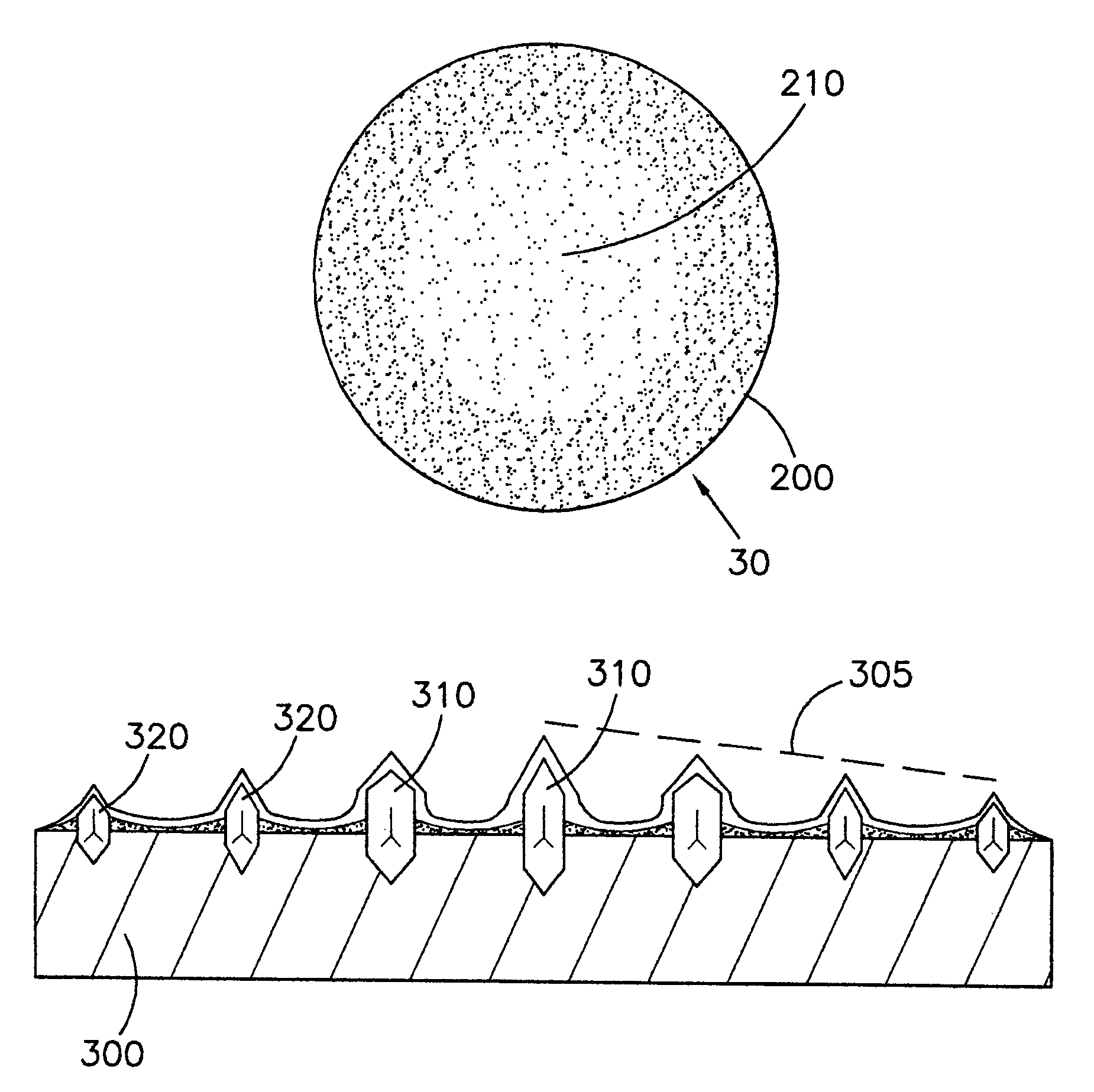
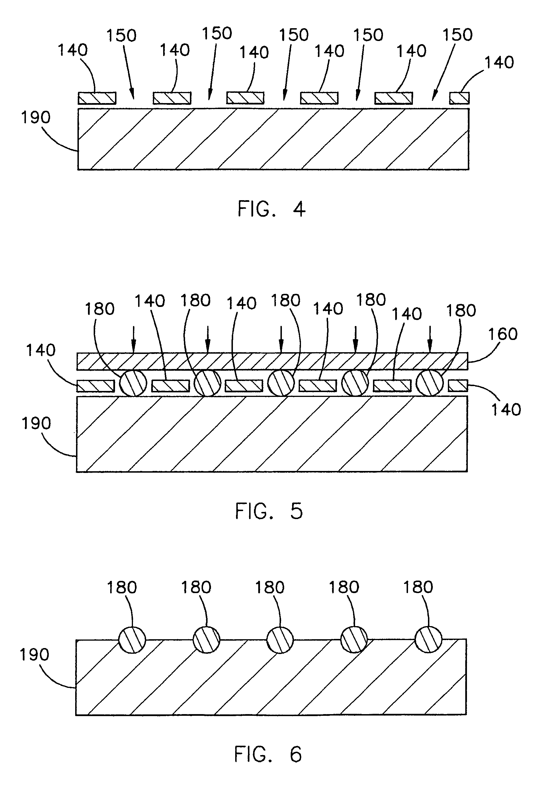
[0016]In addition to the above-recited methods of use, the present invention also includes methods for producing a CMP pad dresser that displays an increased work load on the centrally located superabrasive particles. Generally speaking, such a method includes the steps of: 1) providing a substrate; and 2) attaching a plurality of superabrasive particles on to the substrate in a pattern that reduces the penetration of peripherally located particles into the CMP pad and increases the penetration of the centrally located particles into the CMP pad.
[0017]Using the methods described above, CMP pad dressers exhibiting considerable advantages may be created. For example, the working surface of the CMP pad dresser may be configured to increase the contact of the CMP pad under a central portion of the dresser, rather than overly contacting an outside or “leading edge” thereof. Such increased central contact transfers a portion of the work load from the peripheral area of the dresser to the central area of the dresser, thus lengthening the service life of the dresser and allowing the dresser to more effectively cut into and groom the pad. CMP pad dressers that incorporate such configurations are encompassed by the present invention, including those with specific configurations made to support the methods recited above.

Problems solved by technology

A problem with maintaining the top of the pad is caused by an accumulation of polishing debris coming from the work piece, abrasive slurry, and dressing disk.
This accumulation causes a “glazing” or hardening of the top of the pad, and mats the fibers down, thus making the pad less able to hold the abrasive particles of the slurry, and significantly decreasing the pad's overall polishing performance.
Further, with many pads, the pores used to hold the slurry, become clogged, and the overall asperity of the pad's polishing surface becomes depressed and matted.
Unfortunately, such abrasive disks made by conventional methods exhibit several problems.
First, abrasive particles may dislodge from the substrate of the disk and become caught in the CMP pad fibers.
This leads to scratching and ruin of the work piece being polished.
Second, the production methods of the past tend to produce disks having abrasive particles that are clustered in unevenly spaced groups on the surface of the substrate.
The resultant non-uniform spacing between particles causes some portions of the CMP pad to be overdressed which creates wear marks, while others are underdressed which creates glazing layers.
Third, the abrasive particles of these disks are not configured to penetrate the pad to a uniform depth.
This non-uniformity creates additional uneven dressing of the CMP pad.
Finally, depending on the degree to which the CMP pad is flexible, it may tend to bulge or bubble in front of the initial leading edge of the dresser due to the downward force exerted by the dresser.
Such bulging may cause a depression of the pad to occur as it passes under the remaining portion of the dresser, which may in turn, cause the remaining abrasive particles, especially those that are centrally located on the pad dresser to penetrate the pad less deeply or even skip over the pad entirely.
This uneven work load on the dresser particles may cause the pad to be unevenly dressed, and may also cause the dresser to wear unevenly and become worn out prematurely.
Yet another disadvantage with modern CMP pad dressers is reduced service life of the pad conditioner.
When a flexible CMP pad depresses under the pressure of a dresser excessive wear may occur on the leading edge crystals of the pad conditioner as they will bear the majority of the work load.
This work load mismatch increases the wear rate on the leading edge particles and can cause the dresser to become unusable long before the exhaustion of the centrally located particles.
With respect to particle retention, two factors tend to cause the abrasive particles to dislodge from the pad dresser disks of the prior art.
First, dislodging often occurs due to the inferior method by which the abrasive particles have been attached.
Hence, these particles become easily dislodged upon exposure to strong mechanical forces such as friction.
However, the acids of the chemical slurry can quickly weaken the braze-particle bonds and dislodge the abrasive particles under the friction of pad dressing.
The resultant sequence of alternating polishing and then dressing wastes time, and is inefficient.
Warping of the pad dresser working surface during the brazing process also often causes abrasive particles to dislodge.
Exposure to this extreme heat can cause the working surface of the pad dresser to warp, thus compromising the smoothness and planarity of the pad dresser's working surface.
As a result, the braze portion of the working surface will be rough, having high and low spots.
Such spots are undesirable, as they may cause the braze to begin flaking off, and making micro-scratches on the polished surface of the work piece.
Further, such unevenness may cause issues with further processing of the dresser, and abrasive particle retention.

Method used


Image

  • Contoured CMP pad dresser and associated methods
  • Contoured CMP pad dresser and associated methods
  • Contoured CMP pad dresser and associated methods

Examples


Embodiment Construction

[0030]Before the present CMP pad dresser and accompanying methods of use and manufacture are disclosed and described, it is to be understood that this invention is not limited to the particular process steps and materials disclosed herein, but is extended to equivalents thereof as would be recognized by those ordinarily skilled in the relevant arts. It should also be understood that terminology employed herein is used for the purpose of describing particular embodiments only and is not intended to be limiting.

[0031]It must be noted that, as used in this specification and the appended claims, the singular forms “a,” and, “the” include plural referents unless the context clearly dictates otherwise. Thus, for example, reference to an “abrasive particle” or a “grit” includes reference to one or more of such abrasive particles or grits.

[0032]Definitions

[0033]In describing and claiming the present invention, the following terminology will be used in accordance with the definitions set for...


PUM

PropertyMeasurementUnit
Raaaaaaaaaaa
thicknessaaaaaaaaaa
thicknessaaaaaaaaaa

Abstract

CMP pad dressers with increased pad dressing work loads on the centrally located abrasive particles during dressing of a CMP pad, and methods associated therewith are disclosed and described. The increase in work load on centralized particles improves pad dressing performance and also extends the service life of the pad dresser.

Description

PRIORITY DATA[0001]This patent application is a continuation-in-part of U.S. patent application Ser. No. 10 / 109,531 filed Mar. 27, 2002, now U.S. Pat. No. 6,884,155 which is a continuation-in-part of U.S. patent application Ser. No. 09 / 558,582 filed Apr. 26, 2000, which has now issued as U.S. Pat. No. 6,368,198 which is a continuation-in-part of U.S. patent application Ser. No. 09 / 447,620 filed Nov. 22, 1999, now abandoned, each of which is incorporated herein by reference in their entirety.FIELD OF THE INVENTION[0002]The present invention relates generally to a device and methods for dressing or conditioning a chemical mechanical polishing (CMP) pad. Accordingly, the present invention involves the chemical and material science fields.BACKGROUND OF THE INVENTION[0003]Many industries are now using a chemical mechanical process (CMP) for polishing certain work pieces. Particularly, the computer manufacturing industry has begun to rely heavily on CMP processes for polishing wafers of c...

Claims


Application Information

Patent Timeline
Patent Type & Authority Patents(United States)
IPC IPC(8): B24B21/18B24B53/017B24B53/12B24D3/06B24D7/02
CPCB24B53/017B24B53/12B24D3/06B24D7/02B24D18/00B24D2203/00
Inventor SUNG, CHIEN-MIN
Owner KINIK
Why Eureka
Try Eureka