Leakage sensing and keeper circuit for proper operation of a dynamic circuit

a dynamic circuit and leakage sensing technology, applied in the field of dynamic circuits, can solve the problems of difficulty in ensuring the proper operation of a dynamic circuit, the inability to hold a logic-low voltage, and the inability to maintain a constant 0-level output on the circuit outpu

Inactive Publication Date: 2007-04-10
IBM CORP
View PDF5 Cites 14 Cited by
  • Summary
  • Abstract
  • Description
  • Claims
  • Application Information

AI Technical Summary

Problems solved by technology

However, a disadvantage of a dynamic circuit is the necessity to hold a logic-low voltage, e.g., a “0” voltage, output during an evaluate cycle.
Leakage currents often make it difficult for a 0-level output to be consistently maintained on the circuit output.
It is difficult to guarantee proper operation of a dynamic circuit while at the same time guaranteeing performance in the case where technology applications are not easy to determine prior to circuit design.
A keeper structure sized too large for a particular circuit application increases the difficulty for ensuring a proper evaluate cycle.
A keeper structure sized too small facilitates an evaluation cycle of the dynamic circuit but may disadvantageously fail to hold logic low pre-charge values of the dynamic circuit thus failing to guarantee proper logic operation of the circuit.

Method used


Image

  • Leakage sensing and keeper circuit for proper operation of a dynamic circuit
  • Leakage sensing and keeper circuit for proper operation of a dynamic circuit
  • Leakage sensing and keeper circuit for proper operation of a dynamic circuit

Examples


Embodiment Construction

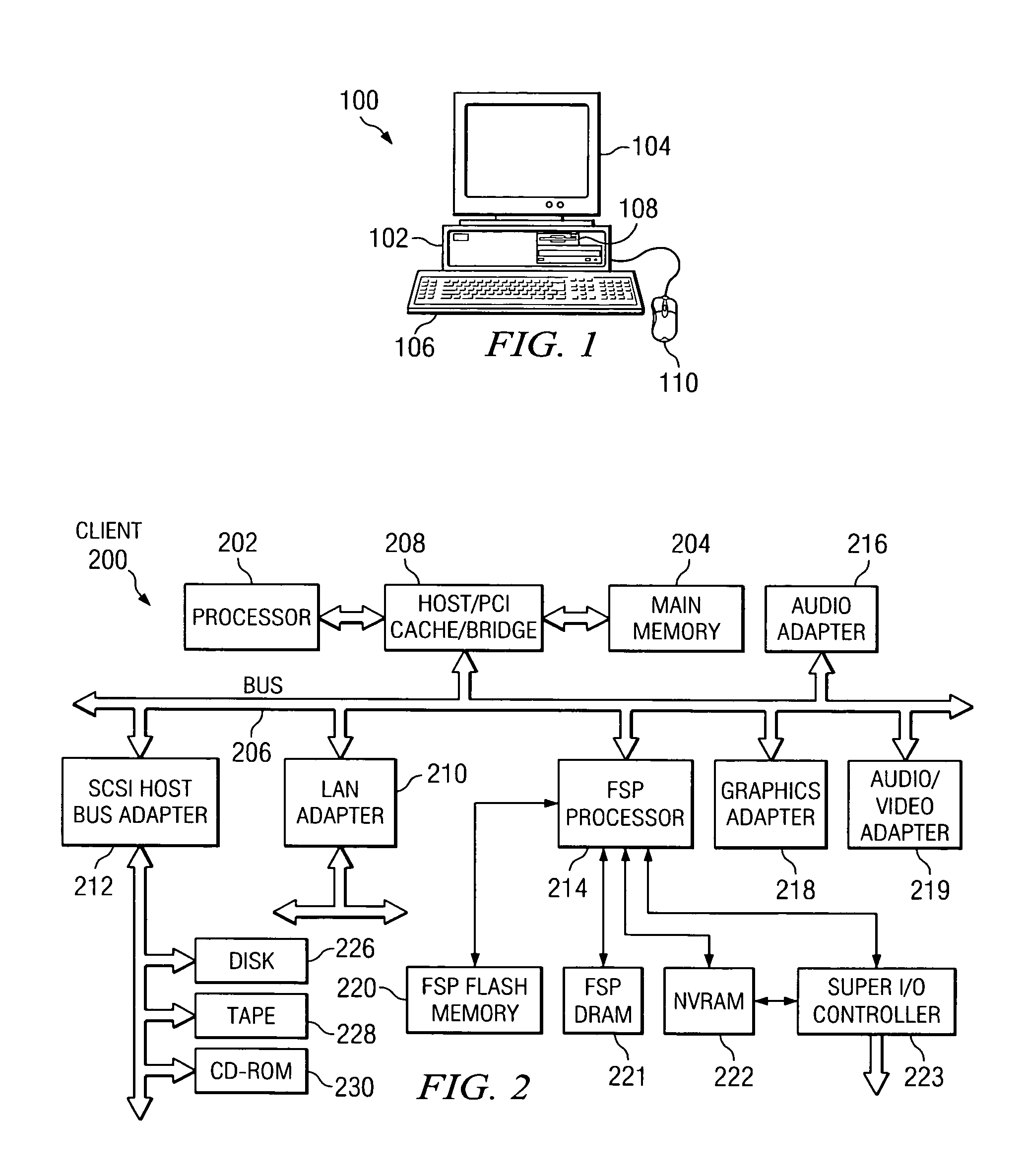
[0013]With reference now to the figures and in particular with reference to FIG. 1, a pictorial representation of a data processing system in which the present invention may be implemented is depicted in accordance with a preferred embodiment of the present invention. A computer 100 is depicted which includes system unit 102, video display terminal 104, keyboard 106, storage devices 108, which may include floppy drives and other types of permanent and removable storage media, and mouse 110. Additional input devices may be included with personal computer 100, such as, for example, a joystick, touchpad, touch screen, trackball, microphone, and the like. Computer 100 can be implemented using any suitable computer, such as an IBM eServer computer or IntelliStation computer, which are products of International Business Machines Corporation, located in Armonk, N.Y. Although the depicted representation shows a computer, other embodiments of the present invention may be implemented in other...


PUM


Abstract

A method and apparatus for ensuring proper operation of a dynamic circuit is provided. A dynamic circuit instance has a plurality of outputs connected to a respective one of a plurality of leakage detector circuits. An output of each leakage detector circuit is connected with a respective one of a plurality of keeper circuits that reside at the dynamic circuit. Each of the plurality of keeper circuits has a unique size ratio with respect to a logic element size of the dynamic circuit.

Description

BACKGROUND OF THE INVENTION[0001]1. Technical Field[0002]The present invention relates generally to dynamic circuits and in particular to a method and apparatus for detecting a leakage current from a dynamic circuit. Still more particularly, the present invention provides a method and apparatus for providing a nominal keeper circuit size for a dynamic circuit based on a detected leakage current of the dynamic circuit.[0003]2. Description of Related Art[0004]Conventional dynamic circuits have many advantages over static circuit counterparts. However, a disadvantage of a dynamic circuit is the necessity to hold a logic-low voltage, e.g., a “0” voltage, output during an evaluate cycle. Leakage currents often make it difficult for a 0-level output to be consistently maintained on the circuit output. Often a keeper structure is added to the circuit for maintaining the 0 voltage.[0005]It is difficult to guarantee proper operation of a dynamic circuit while at the same time guaranteeing pe...

Claims


Application Information

Patent Timeline
Patent Type & Authority Patents(United States)
IPC IPC(8): H03K19/096G01R31/02H03K19/00H03K19/094H03K19/20
CPCH03K19/0963
Inventor CHU, SAM GAT-SHANGKLIM, PETER JUERGENLEE, MICHAEL JU HYEOKPAREDES, JOSE ANGEL
Owner IBM CORP
Why Eureka
Try Eureka