
Method for controlling recording optical power in optical disc device

Active Publication Date: 2007-04-10
HITACHI LG DATA STORAGE KOREA
View PDF2 Cites 1 Cited by
  • Summary
  • Abstract
  • Description
  • Claims
  • Application Information

AI Technical Summary

Benefits of technology

[0007]Therefore, the present invention has been made in view of the above problems, and it is one object of the present invention to provide a method for controlling recording optical power that can optimally control the recording optical power according to a characteristic change of an optical pickup or disc where a recording operation is paused and resumed.
[0008]It is another object of the present invention to provide a method for controlling recording optical power that can control the recording optical power based upon a playback signal of recorded data before a recording operation is paused where the recording operation is paused and resumed.
[0009]It is yet another object of the present invention to provide a method for controlling recording optical power that can improve a playback characteristic of recorded data.

Problems solved by technology

However, the conventional method never takes into account a characteristic change of an optical pickup due to a temperature change or a characteristic change of an inner or outer periphery of the optical disc.
Thus, where a characteristic of the optical pickup or disc is changed and the recording operation is paused and resumed, there is a problem in that the recording operation at optimum recording optical power cannot be appropriately performed and hence a playback characteristic of recorded data is degraded.

Method used


Image

  • Method for controlling recording optical power in optical disc device
  • Method for controlling recording optical power in optical disc device
  • Method for controlling recording optical power in optical disc device

Examples


Embodiment Construction

[0016]Now, preferred embodiments of a method for controlling recording optical power in an optical disc device in accordance with the present invention will be described in detail with reference to the annexed drawings.

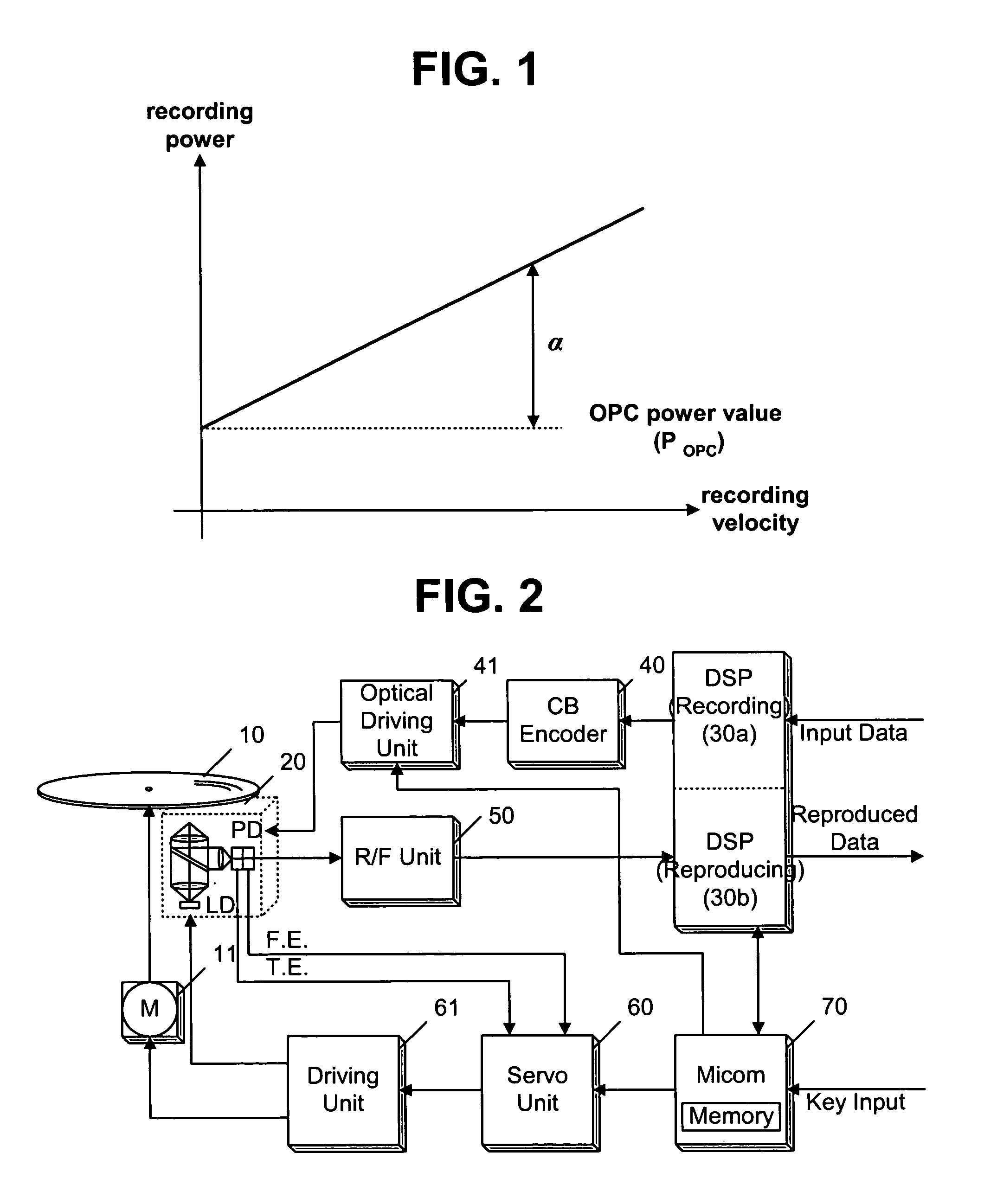
[0017]FIG. 2 is a block diagram illustrating the configuration of an optical disc device in which a method for controlling recording optical power is implemented in accordance with the present invention. In the optical disc device, a digital signal processor (DSP) 30a for recording adds an error correction code (ECC) block, etc. to inputted digital data, and performs a conversion to a corresponding recording format. A channel bit (CB) encoder 40 encodes, into a bit stream, data converted into the recording format. An optical driving unit 41 controls a record signal for the bit stream at predetermined optical drive power and outputs the controlled record signal. An optical pickup 20 records the controlled record signal on an optical disc 10 or reads a signal of recoded...


PUM


Abstract

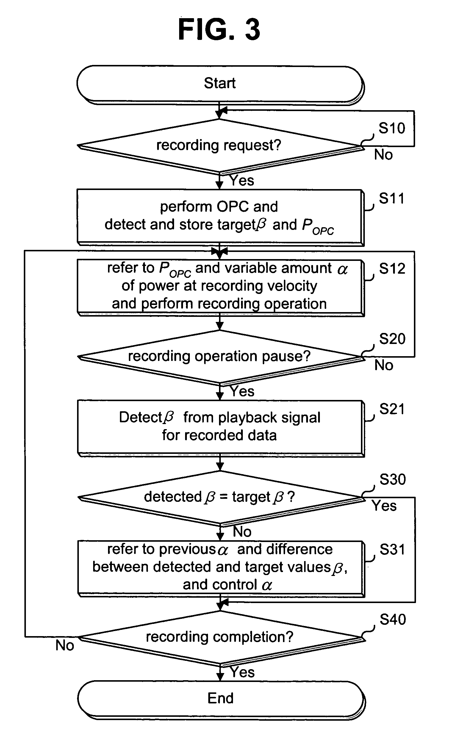
The present invention relates to a method for controlling recording optical power. When a recording operation is paused, a playback signal characteristic for recorded data is detected. The recording optical power is controlled based upon the detected playback signal characteristic and hence the recording operation is resumed at the controlled recording optical power. Therefore, even though a characteristic of an optical pickup or disc varies when the recording operation is paused and resumed, an optimum recording operation can be performed and a playback characteristic for recorded data can be improved.

Description

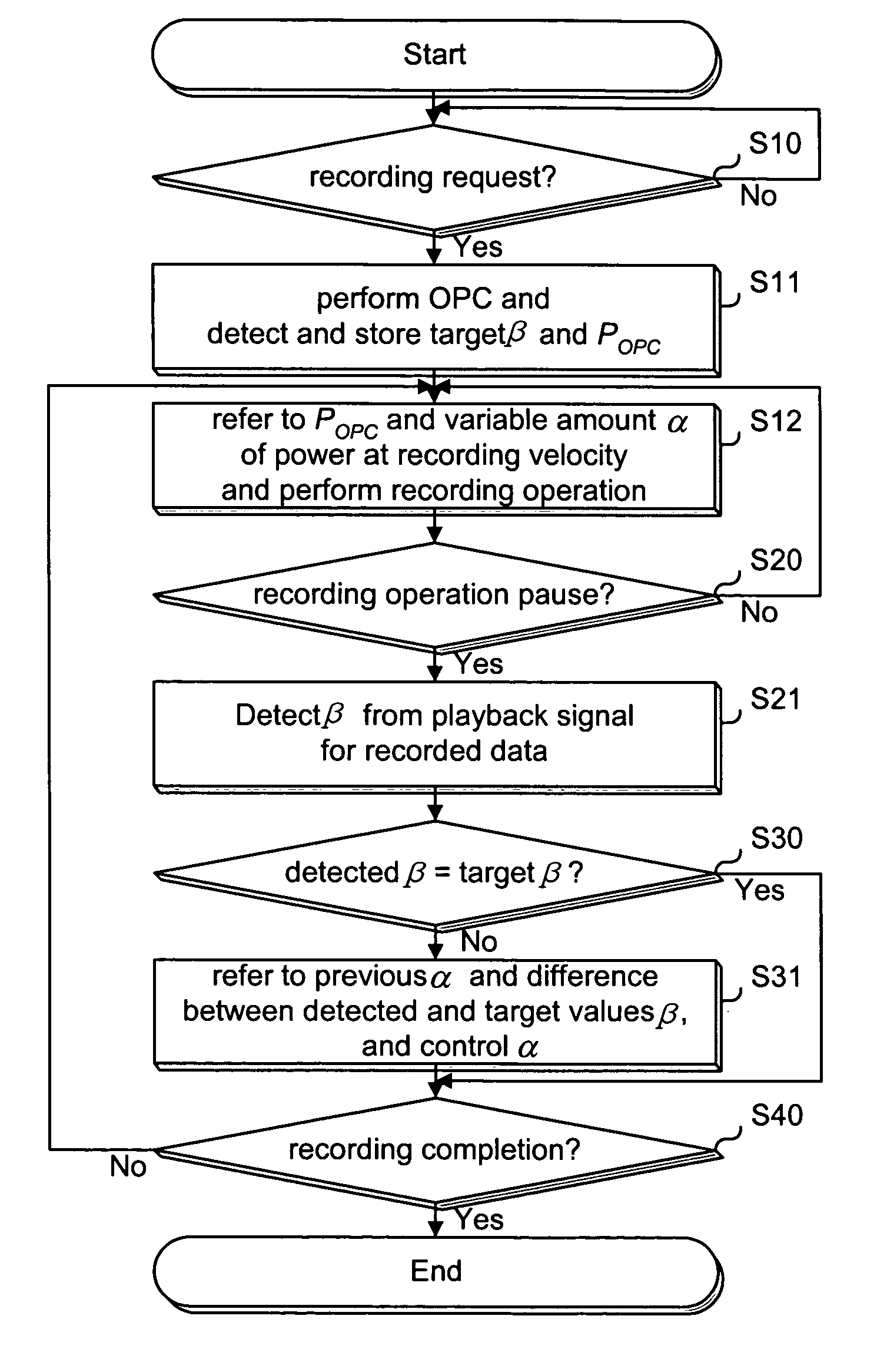
[0001]This Non-provisional application claims priority under 35 U.S.C. § 119(a) on Patent Application No(s). 10-2003-0016934 filed in Korea on Mar. 18, 2003, the entire contents of which are hereby incorporated by reference.BACKGROUND OF THE INVENTION[0002]1. Field of the Invention[0003]The present invention relates to a method for controlling recording optical power in an optical disc device.[0004]2. Description of the Related Art[0005]When recording data on a seated optical disc, an optical disc device detects optimum power calibration (OPC) power Popc through an OPC operation for a test area of the optical disc, and performs a recording operation at a requested recording velocity using the detected OPC power Popc and a variable amount α of power for each recording velocity shown in FIG. 1. The variable amount α of power for each recording velocity shown in FIG. 1 corresponds to an experimental value. In case of the recording operation in a constant angular velocity (CAV) mode, as...

Claims


Application Information

Patent Timeline
IPC IPC(8): G11B7/00G11B7/004G11B5/09G11B7/0045G11B7/125G11B20/18
CPCG11B7/00458G11B7/1267G11B7/004
Inventor CHOI, YOUNG DO
Owner HITACHI LG DATA STORAGE KOREA
Learn More