Image processor

Active Publication Date: 2005-05-31
RICOH KK
View PDF19 Cites 4 Cited by
  • Summary
  • Abstract
  • Description
  • Claims
  • Application Information

AI Technical Summary

Benefits of technology

[0023]It is an object of this invention to provide an image processor which makes effective use of resources in a system for performing multifunction and allows optimal controls as the overall system.

Problems solved by technology

Therefore, the units can not make effective use of the memory module 1006 provided in the copier block, but also provision of plural memory modules for the respective units has led to increased size as an overall apparatus and also increased cost.
Likewise, since the copier block has been established as one system, the functions of the copier block can not efficiently be improved in association with improved performance of peripheral units.
Therefore, it is impossible to easily improve the functions of the overall apparatus in association with improved performance of the peripheral units only by replacing the peripheral units.
These problems may come up not only in the case of peripheral units but also in the case where improvement in functions such as operability of the digital multifunction machine is intended.
Therefore, it is quite impossible for designers to improve the functions of the digital multifunction machine in a simple manner.
Further, the latest algorithm cannot easily be provided to users to utilize the digital multifunction machine.
Further, since the sections forming the copier are established as one system, when the digital multifunction machine is made use of as a scanner or a printer as a single unit, the functions can not easily be separated from each other.
As explained above, in the conventional digital multifunction machine, there has been such a problem that the most appropriate control mechanism is not constructed in the following point of making effective use of resources in the system such as sharing of the module, improvement of the function by replacement for each unit, and division of the function into a plurality of functions.

Method used


Image

  • Image processor
  • Image processor
  • Image processor

Examples


Embodiment Construction

[0036]A preferred embodiment of the image processor according to this invention will be explained in detail below with reference to the attached drawings.

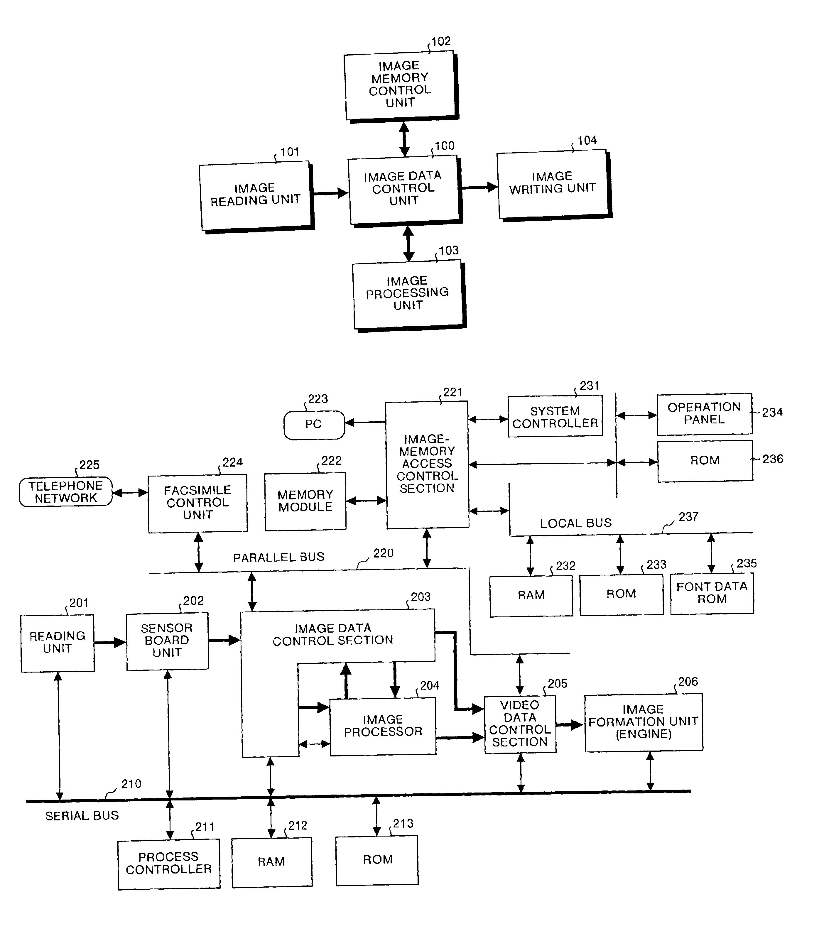
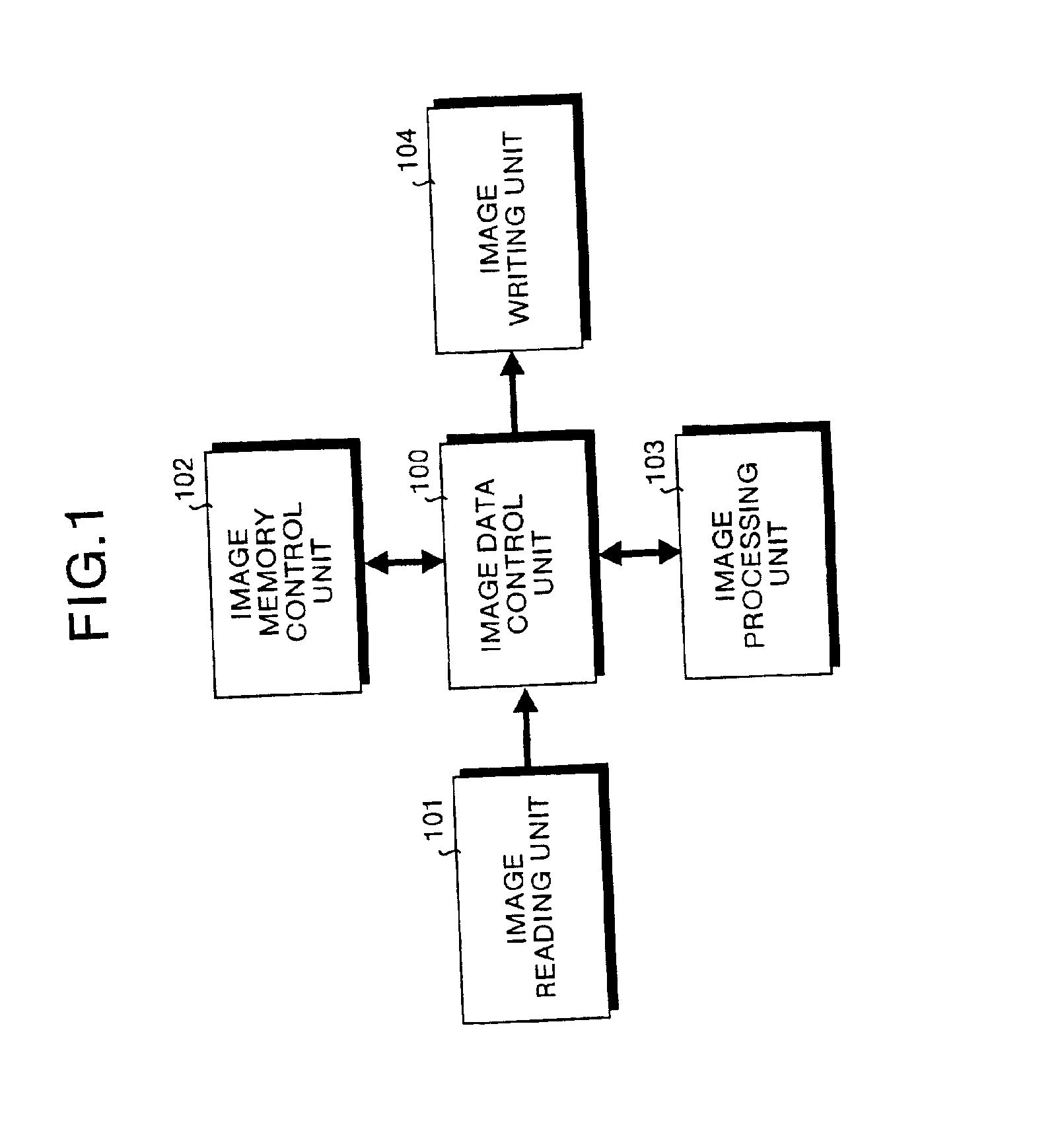
[0037]Principles of the image processor of this embodiment will be explained first. FIG. 1 is a block diagram functionally showing a configuration of the image processor according to the embodiment of this invention. As shown in FIG. 1, the image processor comprises five units as follows.

[0038]The five units are an image data control unit 100, an image reading unit 101 that reads image data, an image memory control unit 102 that controls image memory for accumulating images to execute writing / reading of image data in / from the image memory, an image processing unit 103 that subjects the image data to imaging such as processing and editing, and an image writing unit 104 that writes the image data onto transfer paper or the like.

[0039]The units, that is, the image reading unit 101, the image memory control unit 102, the image processi...


PUM


Abstract

An image processor has a controller unit connected to at least one of functional units such as an image reading unit, detects a source of input of image data according to a network I / F or a parallel bus I / F. An image-memory access control section transmits the image data input from each of the functional units to a memory group and also transmits the image data stored in the memory group to the functional unit. A system controller controls the overall apparatus and also controls the image-memory access control section according to the input source of the image data to determine an order of transmitting the image data to the memory group.

Description

FIELD OF THE INVENTION[0001]The present invention relates to an image processor that processes digital image data obtained, particularly, with a digital multifunction machine. The digital multifunction machine is a machine that can perform the functions of a copier, a facsimile, a printer, and a scanner, or the like.BACKGROUND OF THE INVENTION[0002]Conventionally, analog copiers were known. Recently, digital copiers that process digitized image data have appeared in the market. Further, digital multifunction machines that can perform the functions of a facsimile, a printer, and a scanner in addition to the functions of the digital copier have also come in the market.[0003]FIG. 10 is a block diagram showing a hardware configuration of a conventional digital multifunction machine. This conventional digital multifunction machine is formed with different blocks as follows. One of the blocks comprises a series of components such as a scanning unit 1001, an image processing unit 1002, a v...

Claims


Application Information

Patent Timeline
IPC IPC(8): H04N1/32H04N1/40H04N1/00H04N1/21
CPCH04N1/00915H04N1/32502H04N1/32512H04N1/32587H04N1/32603H04N1/40H04N1/32561H04N1/32358H04N2201/0087H04N2201/0081
Inventor NAMIZUKA, YOSHIYUKIMIYAZAKI, HIDETOMIYAZAKI, SHINYAOTEKI, SUGITAKATAKAHASHI, YUJITONE, TAKEHARUYOSHIZAWA, FUMIOFUKUDA, HIROAKINOMIZU, YASUYUKISATOH, TAKAKOISHII, RIEKAWAMOTO, HIROYUKI
Owner RICOH KK
Why Eureka
Try Eureka