Moisture sensor timer

a technology of moisture sensor and timer, which is applied in the field of timers, can solve the problems of unnecessarily high bills, inefficient use of available water supplies, and water shortages, and achieve the effect of facilitating user scheduling and controlling the operation

Active Publication Date: 2007-04-10
HUSQVARNA AB
View PDF18 Cites 154 Cited by
  • Summary
  • Abstract
  • Description
  • Claims
  • Application Information

AI Technical Summary

Benefits of technology

[0013]The present invention has been developed in response to the present state of the art, and in particular, in response to the problems and needs in the art that have not yet been fully solved by currently available timers. The timer of the invention facilitates a user's scheduling and controlling of the operation of an irrigation system disposed on a property. The irrigation system may include at least a valve, a conduit, and a distribution unit. The distribution unit distributes fluid over an irrigation zone, which is an area of the property. Alternatively, the irrigation system may provide a plurality of irrigation zones; with a plurality of distribution units distributing fluid over each irrigation zone.
[0018]If the timer includes a satellite receiver for communicating with global positioning satellites to receive position data, the position data may be used to determine a location on the map, which may be used to determine the shape, size, and area of the irrigation zone, the property boundaries, and the structures. The position data may also be used to locate each distribution unit of the irrigation system and also to determine the shape, area and location of a portion of the property that is generally populated with a certain plant type. For example, a timer that includes a satellite receiver may be physically moved around the property to obtain position data for the property. The position data can then be used to generate the features of the map such as the property boundaries, the shape, location, and area of irrigation zones, the location of distribution units, and the location and shape of particular areas of the property generally populated with plant type, such as a rose garden or Kentucky blue grass. The position data may be used to improve and better define the map and the relationship of the various map elements displayed on the map.
[0021]The method may also include the steps of determining a soil type of the property and inputting the soil type of the irrigation zone in the memory device. The user may also input the general amount of sunlight the irrigation zone receives during an average day. Using this information, the timer may better determine the desired water coverage for the irrigation zone. By determining the desired water coverage and the amount of water distributed to the irrigation zone over time, the irrigation schedule for the irrigation zone may then be more precisely determined to better provide for the irrigation needs of the irrigation zone without over-watering.
[0030]The timer may also be in communication with sensors so that the timer causes the distribution of fluid to the irrigation zone in response to the sensor information. Specifically, the timer may be in communication with the sensors of a security system so that in response to certain sensor input from the security system, the timer actuates the irrigation system to provide the distribution of fluid to one or more irrigation zones in response to the sensor information. This may be particularly useful in encouraging trespassers to find another route off of the property or encouraging animals to take their business elsewhere. For example, the timer may be in communication with a motion detector or an infrared laser so that when a trespasser is detected in an irrigation zone, the timer opens the valves to the distribution units associated with the irrigation zone to irrigate the area for a short period of time.
[0031]A user may also input irrigation exclusion dates into the timer so that on the selected dates, irrigation is altered or does not occur. For example, the fourth of July may be selected as an exclusion date because the property owner may have friends and family over using the property that night. The timer may also adjust the irrigation of the irrigation zones to accommodate the irrigation exclusion dates so that the plants on the property are not harmed.

Problems solved by technology

The increasing demands for water and occasional droughts have resulted in water shortages.
Additionally, such regulations and guidelines may also provide for fines for watering during daylight hours or wasting water that may result from improper maintenance of an irrigation system
Unfortunately, studies have shown that homeowners consistently apply to their property at least twice as much water as is actually required for healthy growth.
This results in the inefficient use of available water supplies, as well as water bills that are unnecessarily high.
Conversely, property owners may apply too little water to their property, which results in dry areas of their property with dead or weak plants that are more susceptible to weeds and pests.
These dry areas can be unattractive and affect the value and desirability of the property.
In reaction, property owners may over react and apply too much water.
One reason that many property owners commonly over-water or under-water their property is that such property owners are often unaware of the actual irrigation needs of their particular property.
For example, how often a lawn is mowed, fertilized, or treated with pesticides and herbicides can affect the irrigation requirements of the lawn.
Also, the amount of sunlight that each irrigation zone associated with an irrigation system receives can dramatically affect the irrigation requirements of different irrigation zones on their property.
Additionally, given the wide range of plant and soil types, many property owners do not have the knowledge or the resources to determine the irrigation requirements of their property.
While such timers may be convenient, they are also inefficient in that they deliver water based only upon the time of day, regardless of the condition and actual requirements of their property.
Conventional timers are also unable to make adjustments to irrigation when yard care takes place that may affect the irrigation requirements of the property.
Hence, the use of a timer often results in the over-watering of a lawn or garden.
One of the problems with conventional timers is that they rely on a combination of sliding or rotating switches, push buttons, and lighted displays to perform and verify various functions, including setting the time of day, when to water, how long to water, etc.
The way conventional timers are designed, especially the use of multifunction user inputs, reduces the ease of use for the owner.
Additionally, problems with the irrigation system may arise such as clogged distribution units, broken conduits, or broken distribution units.
Currently available timers are unable to clearly direct property owners or caretakers to these problems.
As a result, a user may waste hours, just trying to locate the problem.
The fixed location of the timer may require the user to waste additional time and energy in running back and forth to the timer from various locations on the property in order to discover the precise location of a problem and make repairs to the irrigation system.
Currently available timers are also unable to interact with sensors and other systems, such as security systems, to actuate irrigation at a time not in accordance with the preset irrigation schedule.
For example, a common problem that plagues many property owners are dogs and cats relieving themselves on the property.
Currently, the only remedy is a caretaker chasing away such animals, which is inefficient, time consuming, and ultimately unsuccessful at changing the behavior of the animal.

Method used


Image

  • Moisture sensor timer
  • Moisture sensor timer
  • Moisture sensor timer

Examples


Embodiment Construction

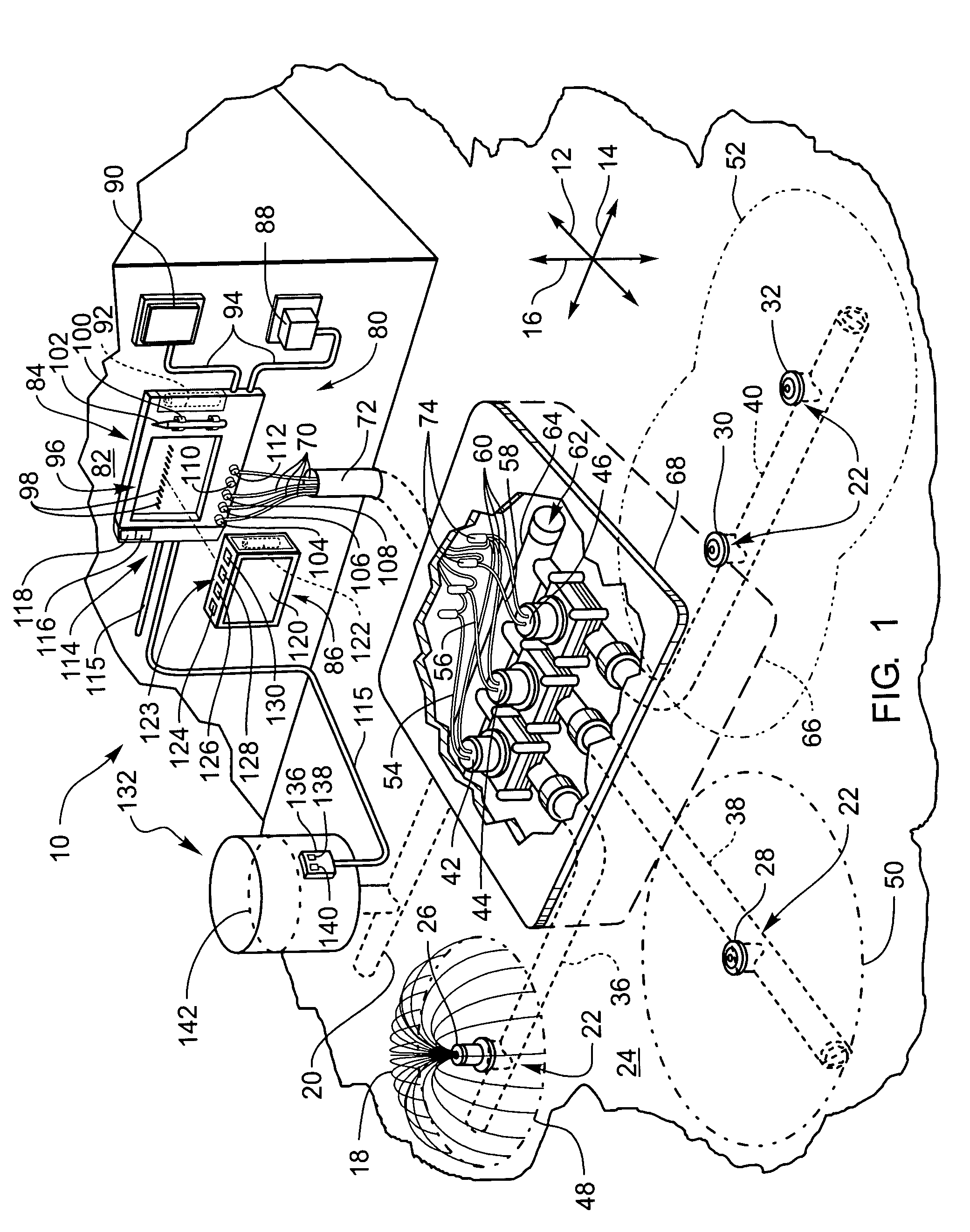
[0051]The presently preferred embodiments of the present invention will be best understood by reference to the drawings, wherein like parts are designated by like numerals throughout. It will be readily understood that the components of the present invention, as generally described and illustrated in the figures herein, could be arranged and designed in a wide variety of different configurations. Thus, the following more detailed description of the embodiments of the apparatus, system, and method of the present invention, as represented in FIGS. 1 through 13, is not intended to limit the scope of the invention, as claimed, but is merely representative of presently preferred embodiments of the invention.

[0052]For this application, the phrases “connected to,”“coupled to,” and “in communication with” refer to any form of interaction between two or more entities, including mechanical, electrical, magnetic, electromagnetic, and thermal interaction. The phrase “attached to” refers to a fo...


PUM


Abstract

A timer that facilitates a user's scheduling and controlling of the operation of an irrigation system for irrigating a property, the timer including a base unit electrically connected to the valve, and a handheld unit including a power source, a CPU, a valve controller, a memory device, and software stored in the memory device. The irrigation system includes a valve, a conduit, and a distribution unit that distributes fluid over an irrigation zone of the property. The handheld unit is used remotely from the base unit to modify an irrigation schedule of the valve. The irrigation schedule is used with the valve controller to operate the valve according to the irrigation schedule through communication with the base unit.

Description

CROSS-REFERENCED RELATED APPLICATIONS[0001]This application claims the benefit of U.S. Provisional Application No. 60 / 543,465, filed Feb. 9, 2004 entitled ENHANCED IRRIGATION TIMER by Chadwick L. Wilson and Christian M. Olsen, which is incorporated herein by reference.BACKGROUND OF THE INVENTION[0002]The present invention relates to timers for controlling the operation of irrigation systems. More specifically, the present invention relates to an improved timer and a method of using a timer to control an irrigation system.[0003]Water conservation is an area of growing concern in today's society. As the population grows, the demand for and consumption of water also increases. The increasing demands for water and occasional droughts have resulted in water shortages. In response to water shortages, many state and local governments have issued guidelines and regulations regarding water consumption in order to promote the conservation and efficient use of available water supplies. Such re...

Claims


Application Information

Patent Timeline
Patent Type & Authority Patents(United States)
IPC IPC(8): G05B11/01B05B12/08B05B17/00
CPCA01G25/165G05B19/0426G05B2219/25249G05B2219/25278G05B2219/2625Y10T137/189
Inventor WILSON, CHADWICK L.OLSEN, CHRISTIAN M.
Owner HUSQVARNA AB
Why Eureka
Try Eureka