High pressure capillary micro-fluidic valve device and a method of fabricating same

a microfluidic valve and high pressure capillary technology, which is applied in the direction of drawing-off water installations, lighting and heating apparatus, and domestic cooling apparatus, etc., can solve the problems of reducing the efficiency of the valve, and limiting the size of the valve, so as to improve the response time and energy consumption of the valve, improve the reliability and fabrication economy, and reduce the effect of thermal stress

Active Publication Date: 2007-04-17
SANDIA NAT LAB +1
View PDF57 Cites 7 Cited by
  • Summary
  • Abstract
  • Description
  • Claims
  • Application Information

AI Technical Summary

Benefits of technology

[0010]Advantages of the valve according to the invention may include fabrication using micro-fabrication techniques to allow for the miniaturization of the valve body beyond the capability of conventional machining techniques. Such implementation advantageously allows for substantial improvements in valve speed, refrigerant consumption, performance reliability and fabrication economy. Micro-fabricated freeze-thaw valves according to the invention can be fabricated as smaller valves to achieve significant improvements in valve response time and energy consumption. Additionally, micro-fabrication of freeze-thaw valves permits the internal features of the refrigerant nozzle, expansion chamber, porous vent, heater and temperature sensor to be fabricated monolithically, i.e. in a single substrate material and thin films, advantageously ensuring the uniformity of the thermal expansion properties and mitigating the effect of thermal stresses. The valve bodies are microfabricated upon silicon substrates. Silicon provides advantageously high thermal diffusivity for fast device speed and low refrigerant and energy consumption, and provides a dual function heating and temperature sensing capability. Micro-fabrication of the valves according to the invention advantageously permits parallel batch fabrication of a plurality of devices of a single embodiment or differentiated, but related embodiments. The range of applications and operational situations of the freeze-thaw valve according to the invention is from stationary applications to battery powered portable applications.

Problems solved by technology

Known freeze-thaw valves are fabricated using conventional machining techniques in three-dimensional geometry and as a result these valves have been limited to larger sizes.
This is undesirable in many applications because the size of the valve affects the valve speed, the refrigerant consumption, the valve reliability and the cost of fabrication.
Thus, freezing and / or thawing a fluid plug takes longer for larger valve bodies than it does for smaller valve bodies.
Moreover, because the refrigerant and electrical energy consumption of the valve is governed by the thermal mass of the valve body, larger valve bodies tend to consume greater amounts of refrigerant and electrical energy than do smaller valve bodies.
Furthermore, the thermal stresses on the valve are governed by the uniformity of the temperature and similarity of the thermal expansion coefficients of the materials used to fabricate the valve, and therefore the reliability and life cycle of the valve are adversely affected by the valve size and material selection.

Method used


Image

  • High pressure capillary micro-fluidic valve device and a method of fabricating same
  • High pressure capillary micro-fluidic valve device and a method of fabricating same
  • High pressure capillary micro-fluidic valve device and a method of fabricating same

Examples


first embodiment

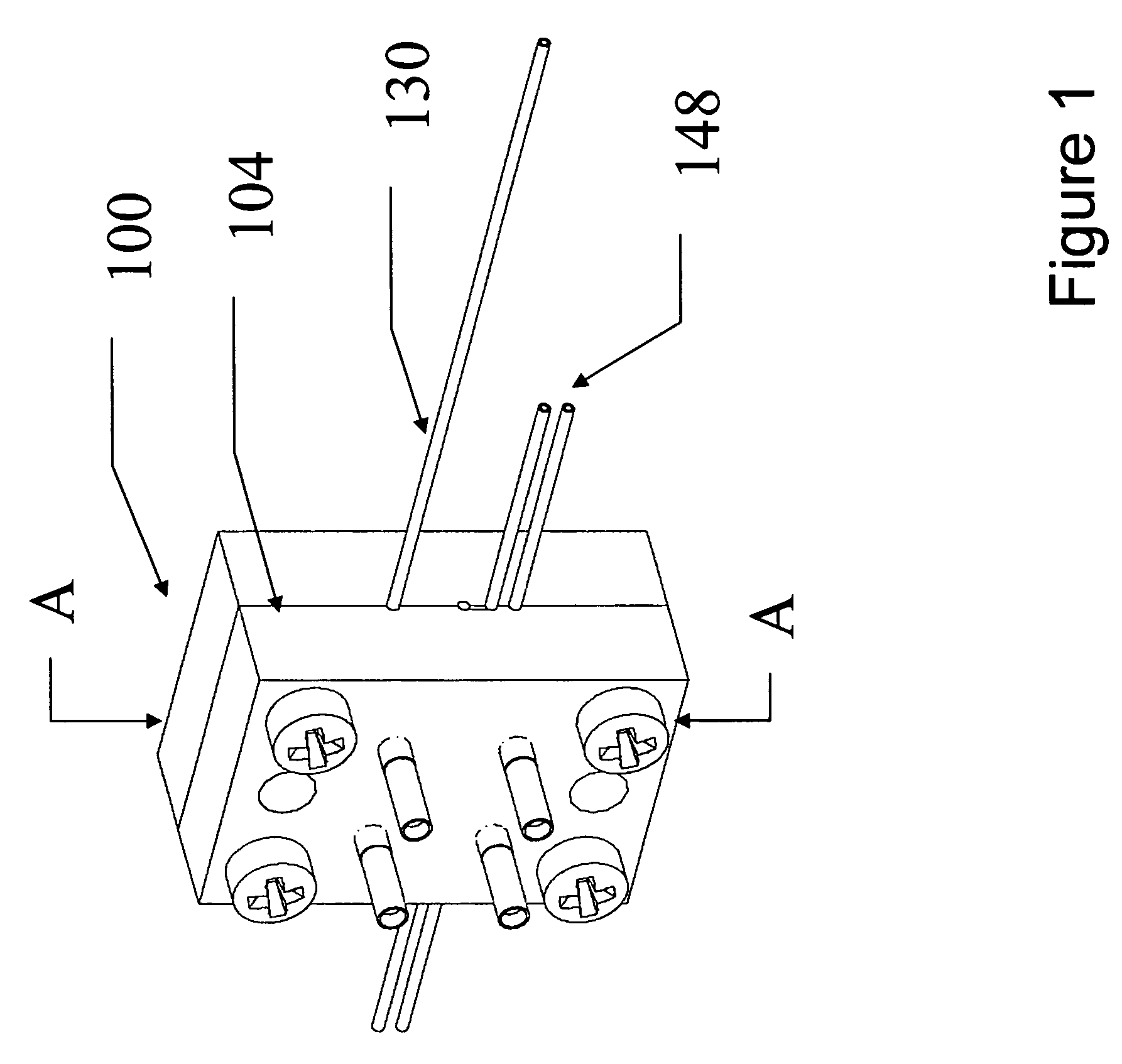
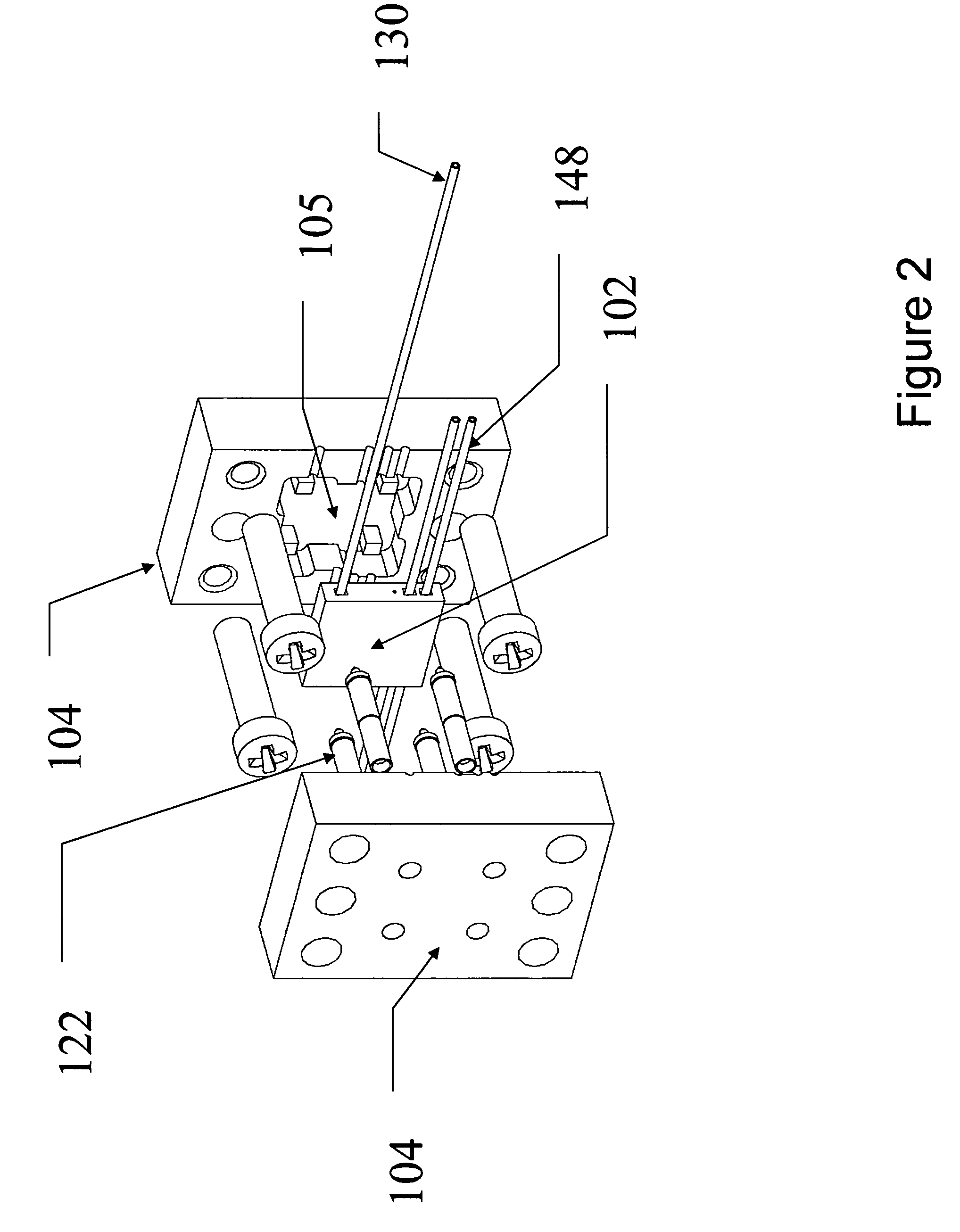
[0029]Referring to FIGS. 1 through 7, a freeze thaw valve 100 includes a valve body 102 (best seen in context in FIG. 2), disposed within a valve housing 104. The valve housing 104 defines a housing cavity 105 for containing valve body 102. Referring to FIGS. 4 and 5, the valve housing 104 includes a housing refrigerant inlet 106, a housing refrigerant vent 108, a working fluid capillary tubing inlet 110, a working fluid capillary tubing outlet 112, and at least one mounting feature 124.

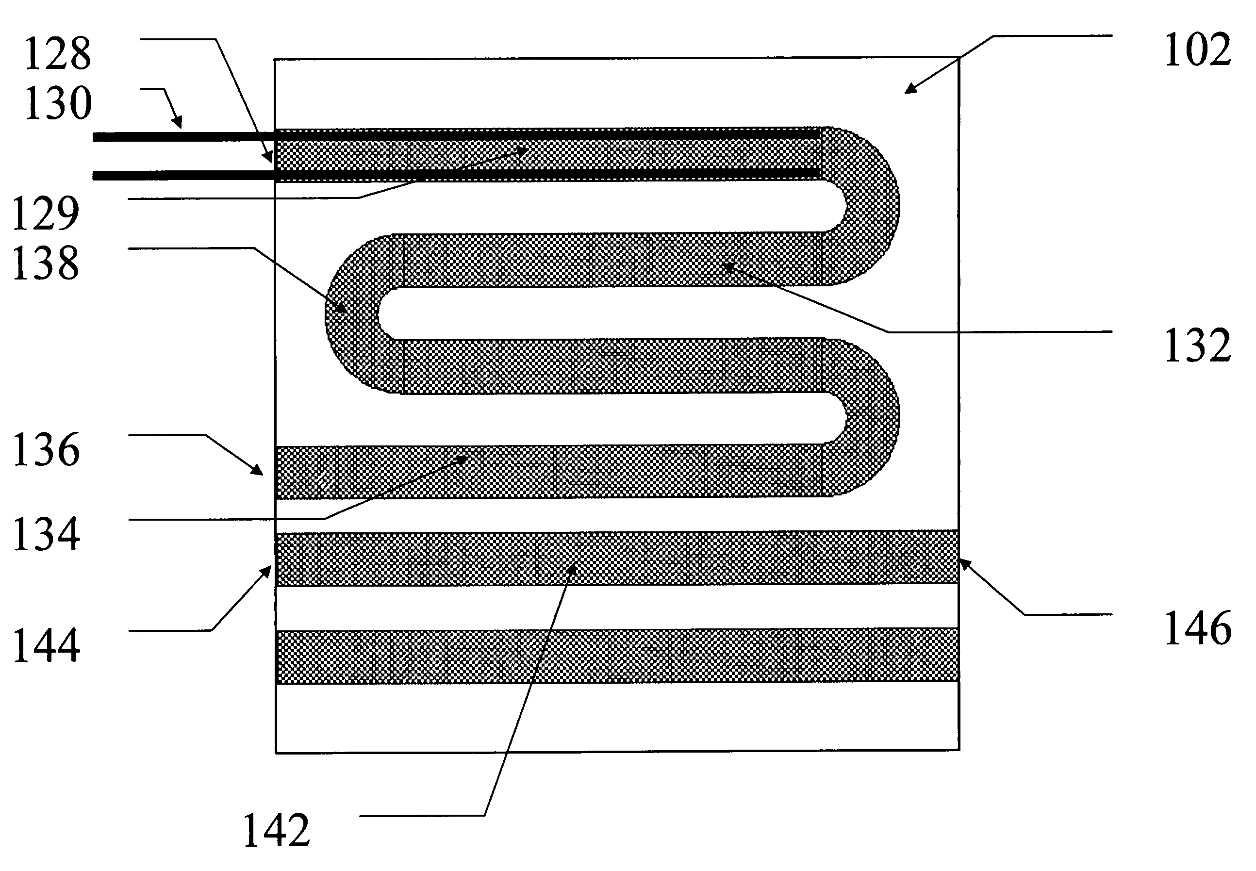
[0030]Valve body 102, best illustrated in FIGS. 6, 7a and 7b, includes a refrigerant inlet 128, a refrigerant supply capillary tube 130 extending therefrom, an expansion chamber 132, a refrigerant vent channel 134 and a refrigerant outlet 136. Expansion chamber 132, which can be implemented in various forms as described hereinafter, is in fluid communication with refrigerant inlet 128 and refrigerant outlet 136. Refrigerant supply capillary tube 130 is disposed, e.g. adhesively bonded, into refrigera...

embodiment 1

[0044]Expansion chamber Referring to FIG. 7a, the valve body 102 may be designed with an expansion chamber consisting of a uniform cross-section channel between the refrigerant inlet 128 and outlet 136. The cross-section dimensions are made for the insertion of the refrigerant supply capillary tube 130 as illustrated in FIGS. 6 and 7a. In this illustrative embodiment the channel advantageously includes serpentine bends to facilitate longer channel length for heat transfer between the vaporizing refrigerant and the valve body 102 and to facilitate the accretion of solid carbon dioxide. The serpentine bends serve the function of flow restriction features 138 (and 140 of the embodiments of FIGS. 9–12), allowing the accretion of carbon dioxide to occlude the refrigerant flow.

embodiment 2

[0045]Expansion chamber Referring to FIGS. 8 and 9, the valve body 102 may be designed with a refrigerant supply capillary tubing conduit 129 in communication with an expansion chamber of smaller uniform cross-section (best seen in FIG. 9), with restrictive serpentine flow restriction elements (140a in FIG. 9), in communication with a refrigerant vent channel 134 disposed between the refrigerant inlet 128 and outlet 136. It should be appreciated that in a microfabricated structure according to the invention, the increasing non-uniform cross-section can be achieved in various ways such as by decreasing the total cross-sectional dimensions as in FIG. 9 or by decreasing the width or depth of an etch such as in FIG. 8.


PUM


Abstract

A freeze-thaw valve and a method of micro-machining the freeze-thaw valve is provided and includes a valve housing, wherein the valve housing defines a housing cavity and includes a housing inlet, a housing vent, a capillary tubing inlet and a capillary tubing outlet. A valve body is provided, at least a portion of which is lithographically constructed, wherein the valve body includes a refrigerant inlet, a refrigerant outlet and an expansion chamber. The expansion chamber is disposed to communicate the refrigerant inlet with the refrigerant outlet and includes a restriction region having a flow restriction. Additionally, the valve body is disposed within the housing cavity to form an insulating channel between the valve housing and the valve body.

Description

CROSS REFERENCED TO RELATED APPLICATIONS[0001]This application claims priority from U.S. Provisional Patent Application Ser. No. 60 / 564,256, filed on Apr. 21, 2004 the contents of which are incorporated herein by reference in its entirety.STATEMENT REGARDING FEDERALLY SPONSORED RESEARCH OR DEVELOPMENT[0002]The U.S. Government has a paid-up license in this invention and the right in limited circumstances to require the patent owner to license others on reasonable terms as provided for by the terms of contract No. DE-AC04-94AL85000 awarded by the U.S. Department of Energy.FIELD OF THE INVENTION[0003]This invention relates generally to an apparatus for controlling a liquid flow through tubing and channels and more particularly to an apparatus for controlling a liquid flow through micro-scale capillary tubing and channels by freezing and thawing the liquid within a segment of the tube or channel.BACKGROUND OF THE INVENTION[0004]The freezing and thawing of a liquid flowing within nano-sc...

Claims


Application Information

Patent Timeline
Patent Type & Authority Patents(United States)
IPC IPC(8): F15C1/04F15C5/00F16K99/00
CPCF15C5/00F16K99/0001F16K99/0003F16K99/0021F16K99/0044F16K2099/0074F16K2099/0084Y10T137/0402Y10T137/1812Y10T137/2196Y10T137/4643F15C1/04F25D3/00
Inventor CROCKER, ROBERT W.CATON, PAMELA F.GERHARDT, GEOFF C.
Owner SANDIA NAT LAB
Why Eureka
Try Eureka