Construction machine

a construction machine and construction technology, applied in the field of construction machines, can solve the problems of difficult to solve the problem of earth accumulation, and achieve the effects of improving mechanical reliability, smooth and effective transfer, and good rigidity

Inactive Publication Date: 2007-04-17
KOMATSU LTD +1
View PDF11 Cites 13 Cited by
  • Summary
  • Abstract
  • Description
  • Claims
  • Application Information

AI Technical Summary

Benefits of technology

[0033]Hence the stress of a load that is transmitted via the upper face plate of the connecting member is transferred smoothly and effectively to the upper face plate of the center frame, which has good rigidity, or the stress of a load that is transmitted via

Problems solved by technology

However, the cover 21 and the like invariably have a level part, and

Method used


Image

  • Construction machine
  • Construction machine
  • Construction machine

Examples


Embodiment Construction

[0043]The present invention will be described in detail below on the basis of the drawings illustrating embodiments thereof.

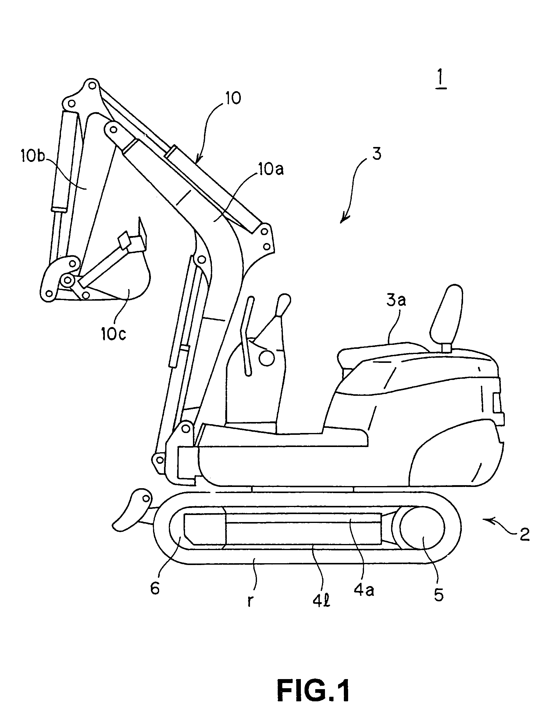
[0044]As shown in FIG. 1, a hydraulic shovel 1 according to this embodiment comprises a lower traveling body 2 to enable motion, and an upper slewing body 3 which is attached slewably to the top of the lower traveling body 2, and which is mounted by an operator to perform an operation.

[0045]An operating seat 3a on which the operator sits to perform an operation is provided on the upper slewing body 3, and a working machine 10 comprising a boom 10a, an arm 10b, and an excavating bucket 10c attached to the tip end of the arm 10b, which are hydraulically driven, is axially supported in a vertical direction so as to swing freely.

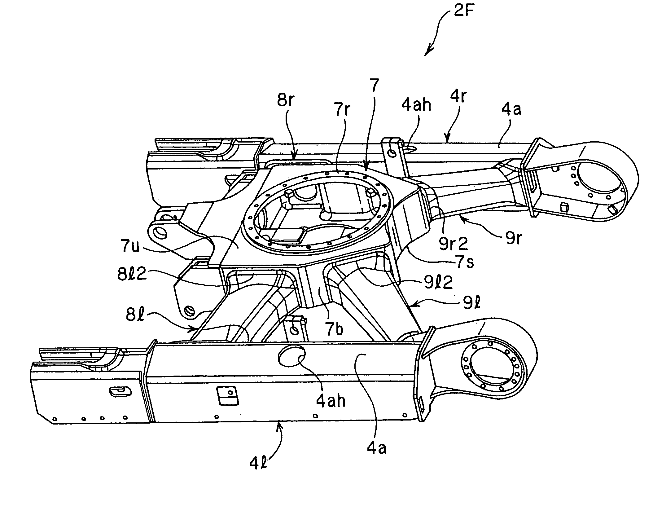
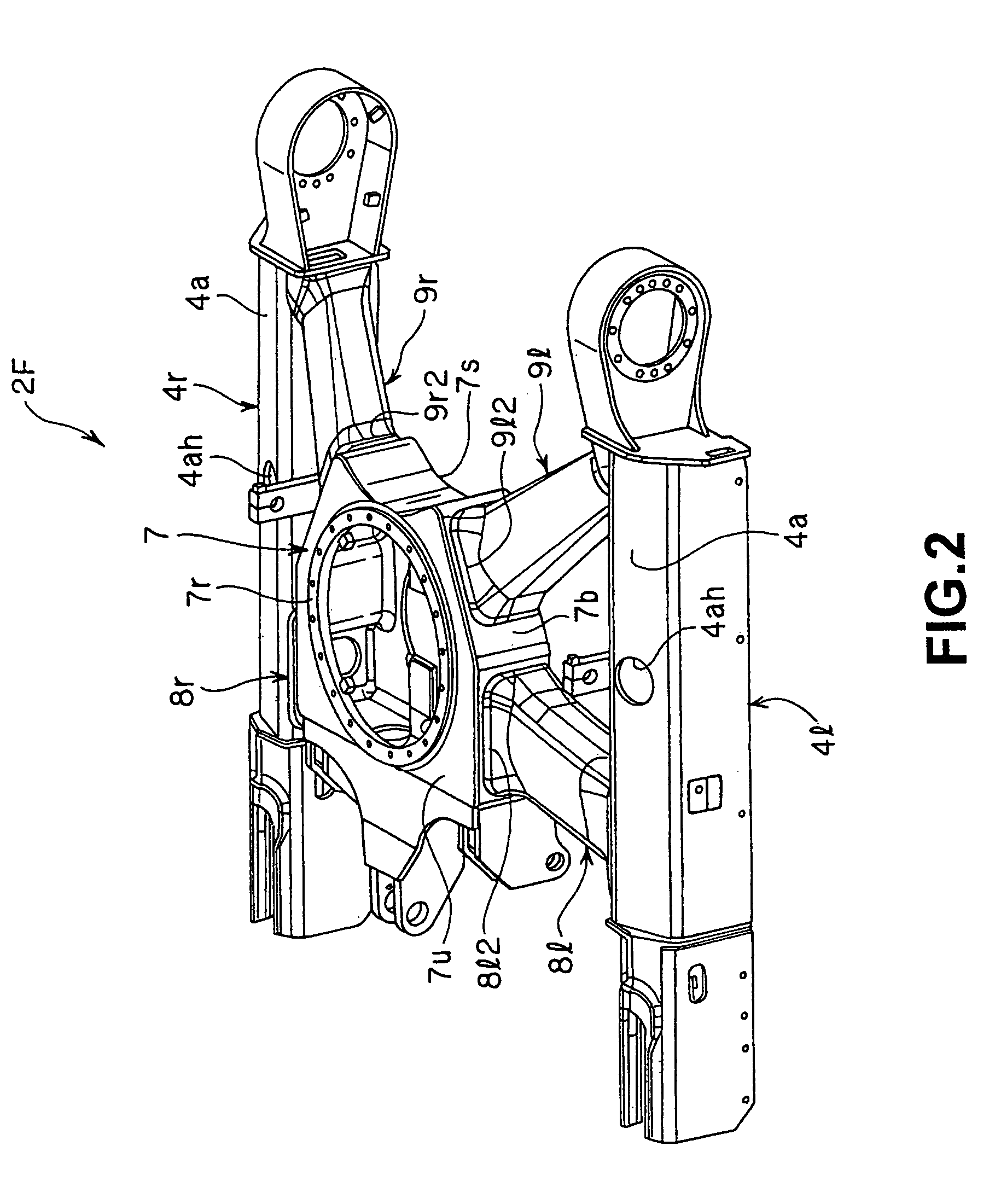
[0046]In the lower traveling body 2, a drive shaft 5 and a pivot 6 are attached respectively to the two end portions of truck frames 4l, 4r, and a crawler belt r is wrapped around the drive shaft 5 and pivot 6.

[0047]The hydraulic shovel 1 i...


PUM


Abstract

A construction machine where a load acting on a vehicle body during an operation is transferred to ensure the strength of the vehicle body, thereby improving reliability including welding reliability. In the construction machine, at least one of the height differences between an upper face or a lower face of the center frame at a joining portion between the center frame and the connecting member and an upper face or a lower face of a center joining portion of the connecting member is set respectively at a dimension that is approximately equal to or less than the thickness of an upper face plate or a lower face plate of the center frame.

Description

BACKGROUND OF THE INVENTION[0001]1. Field of the Invention[0002]The present invention relates to a construction machine such as a hydraulic shovel, and more particularly to a frame constitution of a lower traveling body in a construction machine.[0003]2. Description of the Related Art[0004]As shown in the side view of FIG. 8, a conventional hydraulic shovel 11 comprises a lower traveling body 12 to enable movement, and an upper slewing body 13 which is mounted slewably onto the lower traveling body 12.[0005]In the lower traveling body 12, a drive shaft 15 and a pivot 16 are attached respectively to the two end portions of a truck frame 14, and a crawler belt 17i is wrapped around the drive shaft 15 and pivot 16.[0006]The hydraulic shovel 11 is driven by a power source engine, the power of which is converted into oil pressure by a hydraulic pump to drive a traction motor. This causes the drive shaft 15 to rotate, which drives the crawler belt 17 to rotate, and as a result, traveling ...

Claims


Application Information

Patent Timeline
IPC IPC(8): B62D24/00B62D21/18B62D55/10E02F9/02E02F9/06
CPCE02F9/02A63B69/004B05B9/00A63B71/02A63F9/00A63B69/331
Inventor KUBO, YOSHITERUSENBA, SHINICHINOGUCHI, JUNURASE, KOUHEINISHIMURA, TAKAHARU
Owner KOMATSU LTD
Why Eureka
Try Eureka