
Casting ladle

a technology of casting ladle and cylinder head, which is applied in the direction of manufacturing converters, blast furnace components, blast furnaces, etc., can solve the problems of low thermal conductivity, achieve low thermal conductivity, reduce heat loss, and facilitate handling

Active Publication Date: 2007-04-17
PYROTEK ENG MATERIALS
View PDF10 Cites 4 Cited by
  • Summary
  • Abstract
  • Description
  • Claims
  • Application Information

AI Technical Summary

Benefits of technology

[0010]Composite ceramic materials are very light as compared to cast iron, and ladles made of this material are therefore much easier to handle than traditional cast iron ladles. This allows less powerful handling equipment to be used and / or larger quantities of liquid metal to be transported. They also have a very low thermal conductivity, and the liquid metal therefore loses heat far less rapidly than in a cast iron ladle. This allows the temperature of the foundry furnace to be reduced, leading to a significant saving in energy costs. We have also found that this can lead to a significant reduction in cracking of the moulded products, and therefore a reduced rejection rate.
[0011]Another advantage of the ceramic composite material is that it is not wetted by the liquid metal. The metal therefore pours easily from the ladle, leaving the ladle clean. Also, because it has a lower thermal conductivity than cast iron, the metal does not solidify as quickly within the ladle. It is therefore unnecessary to clean the ladle between casting operations. Furthermore, a release agent applied to the ladle lasts much longer than with a cast iron ladle, so further reducing maintenance requirements and production costs.
[0012]The composite ceramic material is a laminated material that includes multiple layers of woven fiber reinforcing fabric, which extend throughout the base and walls of the ladle. As a result, the ladle is very strong and durable, and is entirely self-supporting, thereby avoiding the need for an internal metal shell. The composite ceramic material preferably includes between two and twenty-five layers of reinforcing fabric, preferably between four and twenty layers. Typically, a casting ladle may include approximately ten layers of reinforcing fabric. The reinforcing fabric is preferably made of woven glass.
[0013]The casting ladle includes a support element, which allows the ladle to be attached easily to a handling device such as a mechanical or robotic arm, or one or more manual lifting handles.

Problems solved by technology

They also have a very low thermal conductivity, and the liquid metal therefore loses heat far less rapidly than in a cast iron ladle.
It is therefore unnecessary to clean the ladle between casting operations.

Method used


Image

  • Casting ladle
  • Casting ladle
  • Casting ladle

Examples


Embodiment Construction

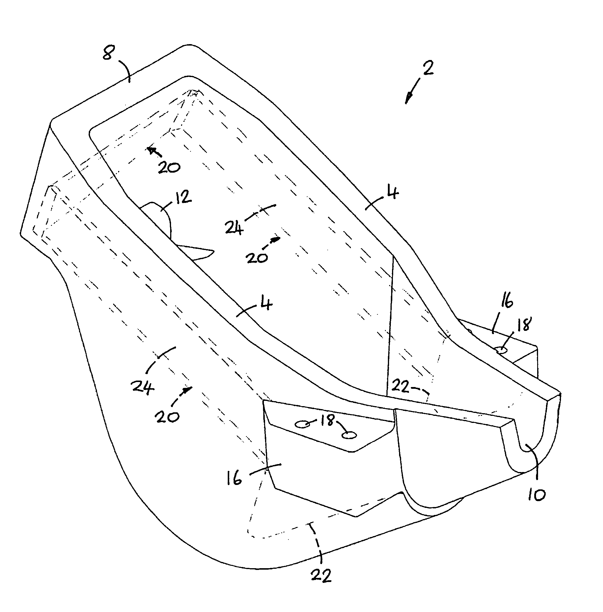
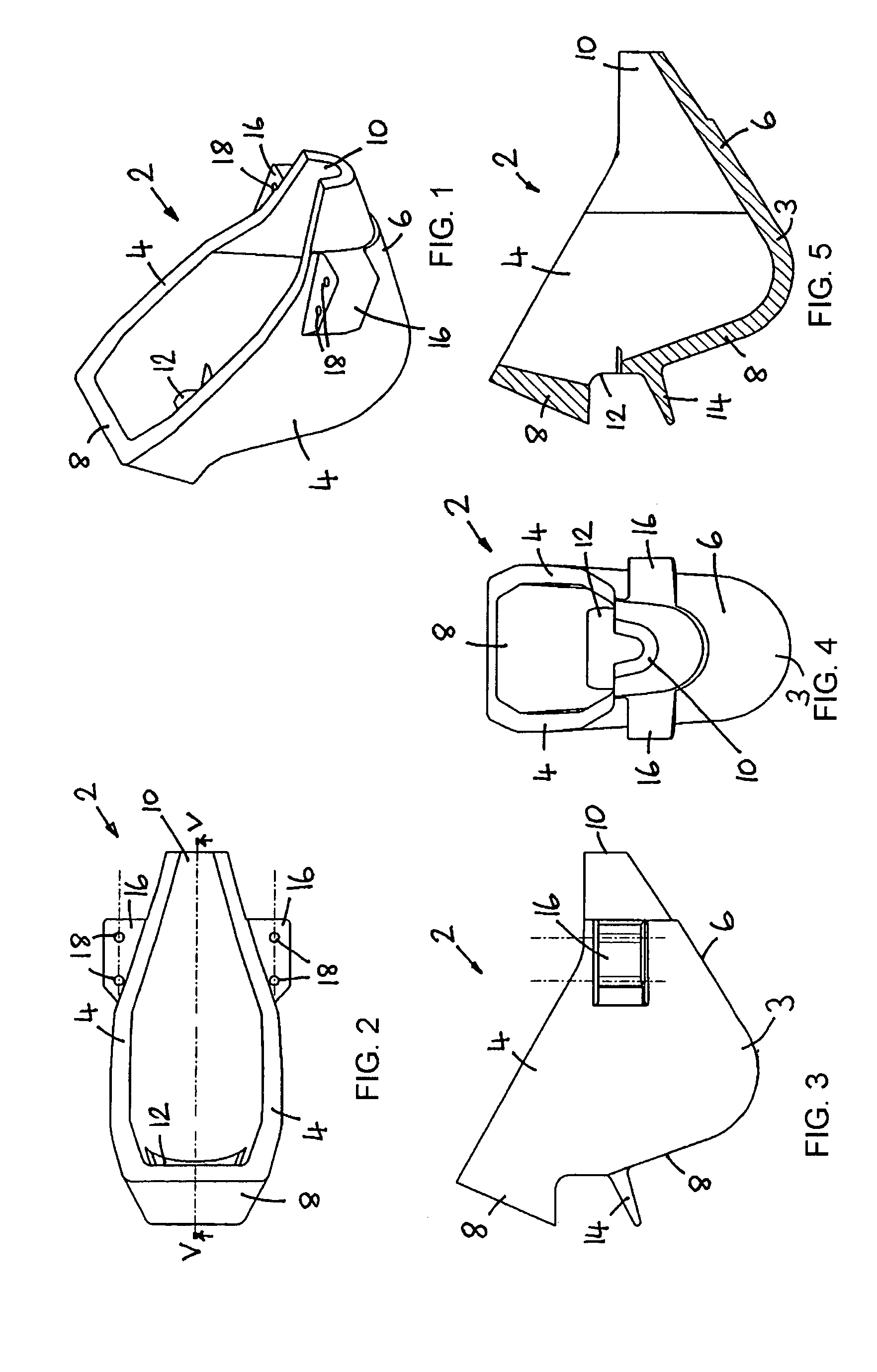
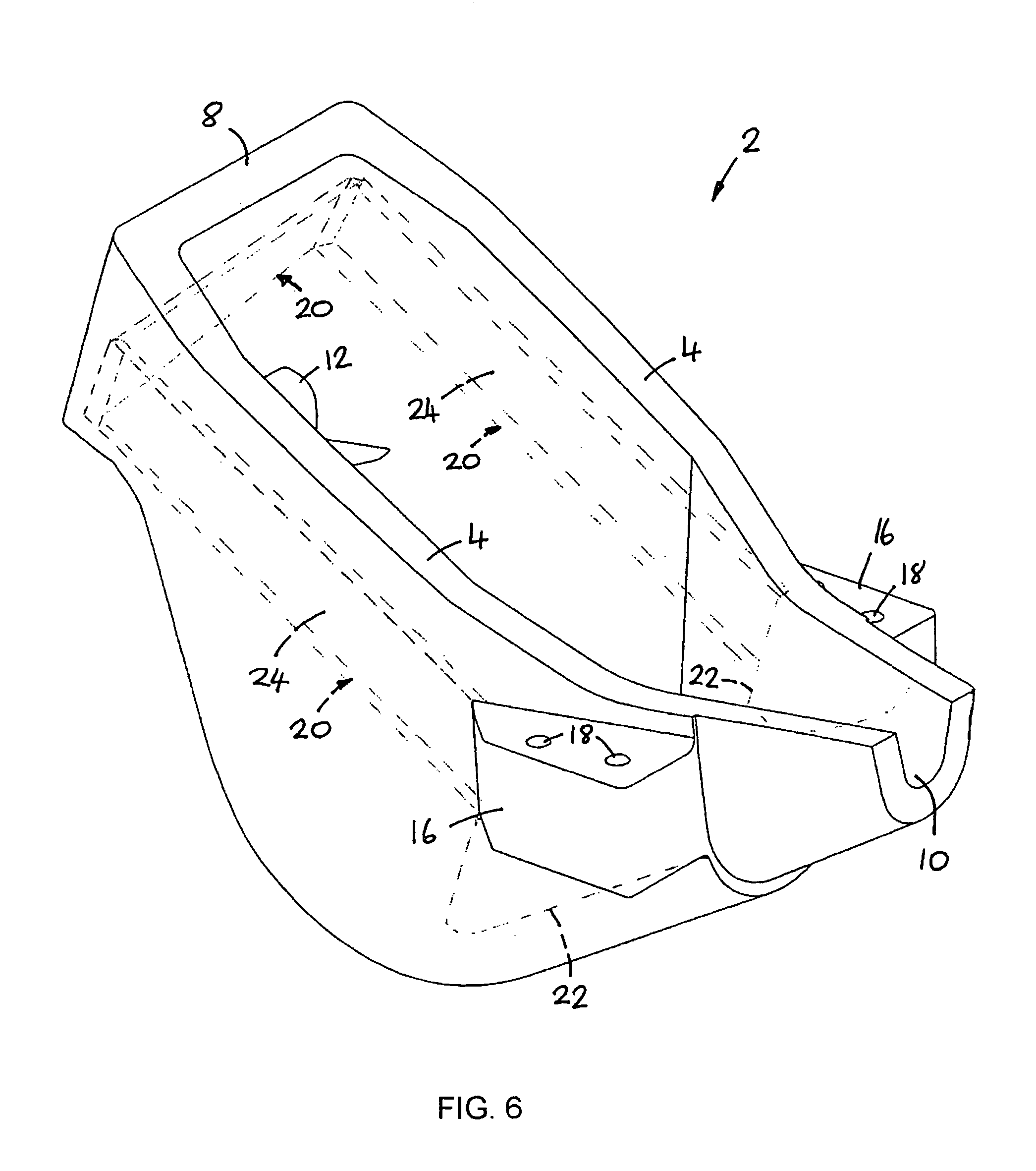
[0032]The casting ladle shown in FIG. 1 comprises an open topped vessel 2 having a base 3, two side walls 4, an inclined front wall 6, an inclined rear wall 8, and a pouring spout 10. An inlet opening 12 is provided in the rear wall 8, below which there is provided an outwardly extending scraper fin 14. A mounting block 16 is provided on each side of the ladle, each mounting block having two cylindrical bores 18 for receiving mounting bolts (not shown). The mounting blocks 16 are used for attaching the ladle to a handling device, such as a robotic arm or one or more manual lifting handles (not shown).

[0033]The ladle shown in FIG. 1 has a capacity of approximately 2 litres and is capable of carrying approximately 5 kg of liquid aluminium. The wall thickness of the ladle is generally approximately 12 mm, and ranges from approximately 8 mm adjacent the spout 10 to approximately 20 mm above the inlet opening 12.

[0034]The casting ladle is made from a laminated composite ceramic material ...


PUM

PropertyMeasurementUnit
thicknessaaaaaaaaaa
thicknessaaaaaaaaaa
thicknessaaaaaaaaaa

Abstract

A casting ladle has a body (2) with a base (3) and walls (4, 6, 8) made of a laminated composite ceramic material that includes multiple layers of a woven fiber reinforcing fabric embedded in a ceramic matrix. A rigid support element (20) for attaching the ladle to a handling device is embedded within the composite ceramic material. In a preferred form, the reinforcing fabric is made of woven glass and the matrix material includes calcium silicate and silica.

Description

BACKGROUND OF THE INVENTION[0001]1. Field of the Invention[0002]The present invention relates to a casting ladle for use in metal foundries and in particular, but not exclusively, to a ladle for casting aluminium and aluminium alloys, and other non-ferrous metals such as zinc.[0003]2. Description of the Related Art[0004]In aluminium foundries where castings are made using either high pressure die casting or gravity die casting techniques, ladles are normally used for transporting pre-measured quantities of liquid metal from a holding furnace to a casting machine and then pouring the liquid metal into a receptacle of the casting machine. For large scale production processes, the ladle is normally mounted on a mechanical or robotic handling device, which is programmed to dip the ladle into the holding furnace to obtain a measured quantity of liquid metal, and then transport the metal and pour it into the casting machine. For smaller scale production processes, the ladle can be handled...

Claims


Application Information

Patent Timeline
Patent Type & Authority Patents(United States)
IPC IPC(8): C21B3/00B22D17/30B22D41/02B22D41/04
CPCB22D41/02B22D41/04
Inventor VINCENT, MARK
Owner PYROTEK ENG MATERIALS
Learn More