Snap fit electrical connector assembly with operating tool for facilitating the connection of a connector assembly to an electrical box

a technology of electrical connectors and operating tools, which is applied in the direction of coupling device connections, connection contact member materials, coupling protective earth/shielding arrangements, etc., can solve the problems of installation or user not having a general sufficient access to the connector assembly, installer or user exerting a severe pulling force, and difficult connection of such “snap-fit” connectors to an electric box concealed in a finished wall. , to achieve the effect of reducing the number of components, simple structur

Active Publication Date: 2007-04-17
BRIDGEPORT FITTINGS LLC
View PDF60 Cites 40 Cited by
  • Summary
  • Abstract
  • Description
  • Claims
  • Application Information

AI Technical Summary

Benefits of technology

[0008]Another object is to provide a connector assembly having an outlet end about which there is disposed a retaining ring having an opening sized to receive the working end of a tool functioning as a lever to transmit a pulling force on the connector and associated retaining ring to pull the connector and associated retaining ring through a knockout hole to seat and lock the connector assembly to the electric box with a minimum of effort or force.
[0036]A still further embodiment of the invention utilizes a modified connector body provided with a frustro conical outlet end having a frustro conical shaped external snap fit retaining ring by which the connector assembly can be readily attached to an electrical panel or electrical box by a snap fit, and having a uniquely formed wire retainer device that clips onto the inlet end of the connector body and is externally secured to the connector body for enhancing ease of assembly while providing the wire retainer to extend into the inlet end of the connector body with sufficient flexibility and range of movement for retaining a wire conductor or conductor sheath within the connector body in a manner to prohibit any unintentional separation of the wire conductor or sheath from the connector body.

Problems solved by technology

While “snap fit” connectors have been in use for some time, the attachment of such “snap-fit” connectors to an electric box which is concealed in a finished wall is difficult, if not impossible.
For this reason, the installer or user does not have generally sufficient access to the connector assembly so as to apply the necessary force to manually pull the leading end of the connector assembly through the knockout hole due to the relative rigid flexibility of the locking tangs in order to seat and lock the connector assembly to the knockout opening.
Usually, the installer or user has to exert a severe pulling force on the wires extending through the connector assembly to seat and lock a snap-fit connector assembly in the knockout hole of an electric box.
Applying such pulling force directly on the wires to lock a snap-fit connector assembly to an electric box could seriously damage the conducting wires.

Method used


Image

  • Snap fit electrical connector assembly with operating tool for facilitating the connection of a connector assembly to an electrical box
  • Snap fit electrical connector assembly with operating tool for facilitating the connection of a connector assembly to an electrical box
  • Snap fit electrical connector assembly with operating tool for facilitating the connection of a connector assembly to an electrical box

Examples


Embodiment Construction

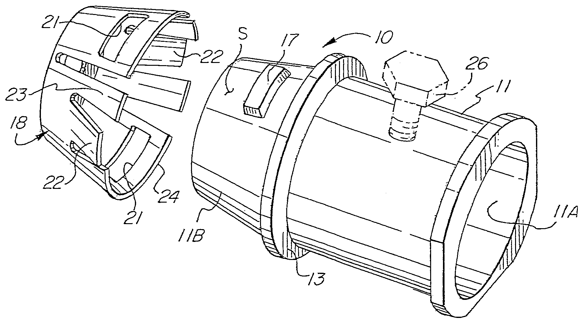
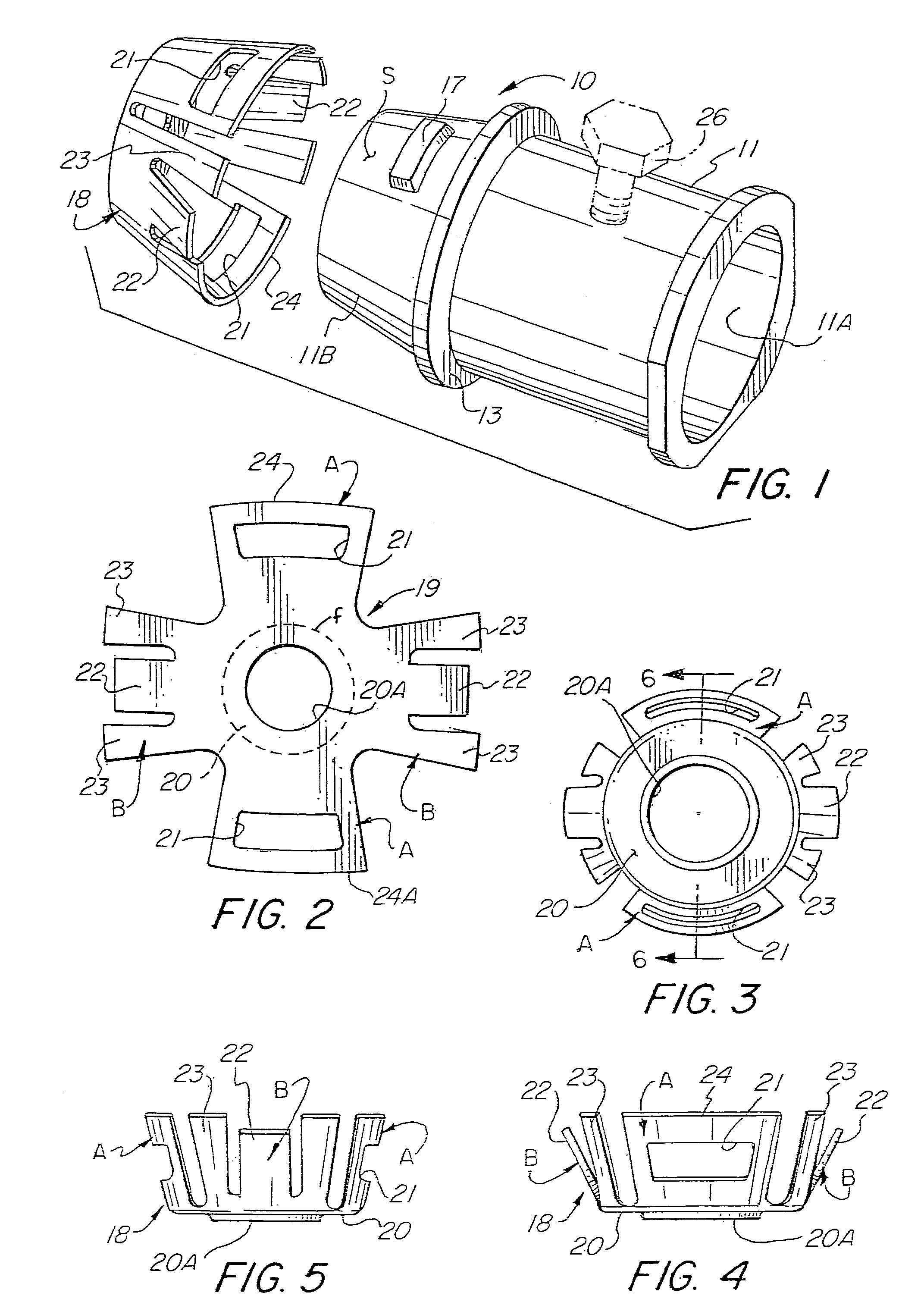
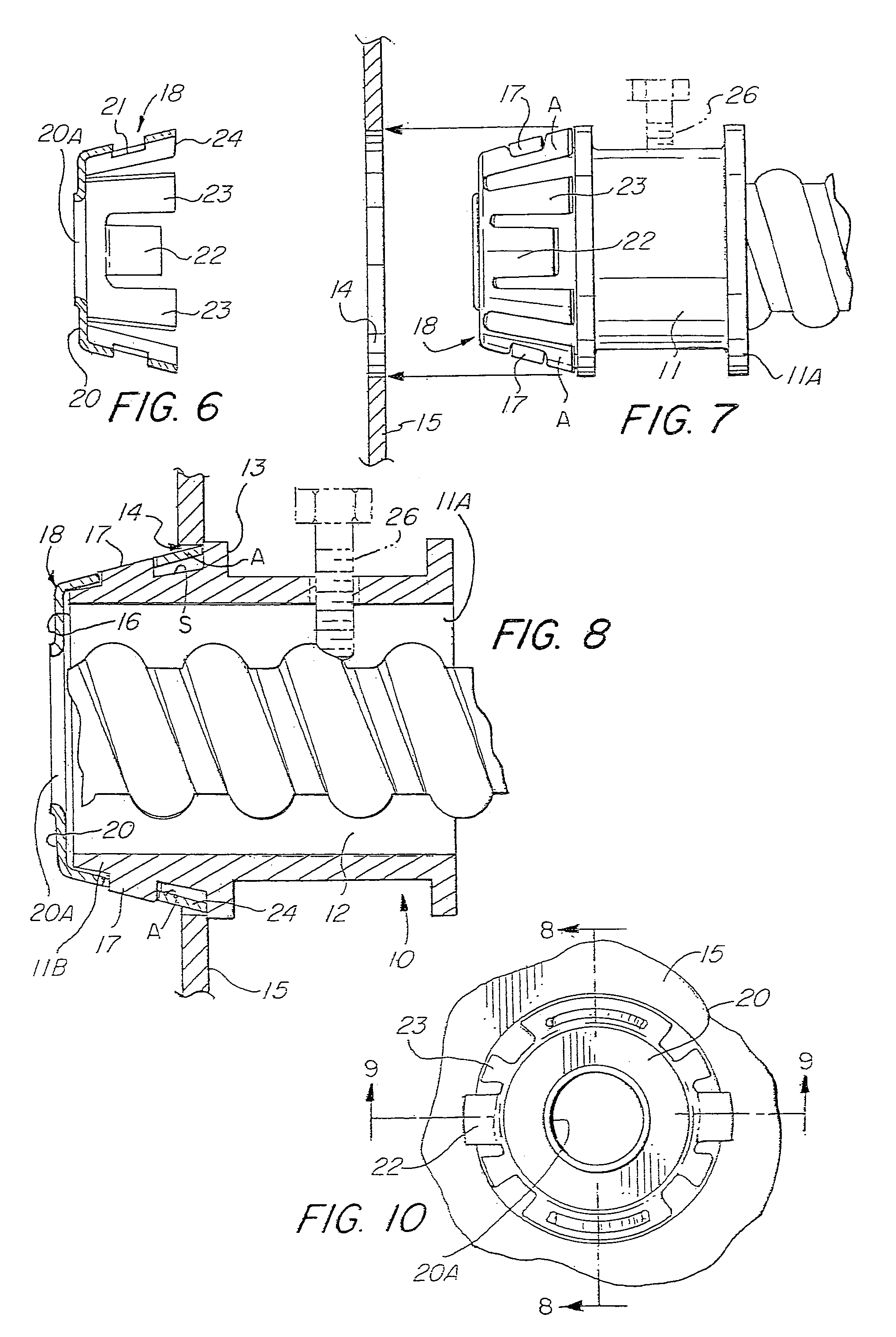
[0096]Referring to the drawings, there is shown in FIG. 1 an electrical connector assembly 10. The connector assembly 10 includes a connector body 11, which is usually formed of metal casting, e.g. zinc or other suitable metallic alloy. The connector body 11 is formed with an inlet end portion 11A and an outlet end portion 11B and having a bore 12 extending therethrough. Intermediate the connector body 11 or between the inlet end portion 11A and outlet end portion 11B there is provided a radially outwardly extending flange 13 which functions as a stop to limit the amount that the connector body 11 may be inserted through the knockout hole 14 of an electric box 15, as noted in FIG. 8.

[0097]As shown in FIGS. 1 and 8, the outer surface S of the outlet end portion 11B slopes, tapers or converges toward the outlet opening 16 whereby the outer surface S of the outlet end portion 11B has a generally frustro-conical configuration. Formed on the surface S of the outlet end portion 11B is an ...


PUM


Abstract

An electric connector assembly having a connector body defining an inlet end portion and an outlet end portion and having a frustro-conical retainer ring connected to the outlet end portion wherein the retainer ring is formed with locking and grounding tangs arranged to effect a snap-fit locking and grounding connection to a knockout hole of an electric box located in an existing wall and a tool arranged to engage slots formed in the retainer ring to facilitate the pulling of the connector assembly through the knockout hole of an electric box for seating and locking the electric connected thereto, and a method for securing the electrical connector assembly to an electric box installed in a finished wall.

Description

RELATED APPLICATIONS[0001]This application is a continuation in part application of a continuation in part application of application Ser. No. 11 / 258,990 filed Oct. 26, 2005, now U.S. Pat. No. 7,057,107 which is a continuation in part of application Ser. No. 11 / 151,374 filed Jun. 13, 2005 now U.S. Pat. No. 7,075,007 for Snap Fit Electrical Connector Assembly With conical Outer Snap Fit Retainer And One Or More Internal Snap Fit Wire Retainers, which is a continuation in part of application Ser. No. 11 / 100,250 filed Apr. 6, 2005 now U.S. Pat. No. 7,064,272 for Snap In Electrical Connector Assembly With Unidirectional Wire Conductor Retainer Ring, which is a continuation in part application of application Ser. No. 10 / 939,619 filed Sep. 13, 2004 for Electrical Connector With Frustro Conical Snap Fit Retaining Ring, now U.S. Pat. No. 6,916,988 B1.FIELD OF THE INVENTION[0002]This invention is directed to a further advancement in the field of electrical connector assemblies having a snap ...

Claims


Application Information

Patent Timeline
Patent Type & Authority Patents(United States)
IPC IPC(8): H02G3/06
CPCH01R4/646H01R13/741H02G3/0683H02G3/0691H01R4/36H01R43/26
Inventor AURAY, DELBERTKIELY, KENNETH M.
Owner BRIDGEPORT FITTINGS LLC
Why Eureka
Try Eureka