Pulse width modulator quantisation circuit

a modulator and pulse width technology, applied in the direction of pulse conversion, instruments, code conversion, etc., can solve the problems of extra quantisation error and hence distortion

Active Publication Date: 2007-04-17
CIRRUS LOGIC INC
View PDF17 Cites 21 Cited by
  • Summary
  • Abstract
  • Description
  • Claims
  • Application Information

AI Technical Summary

Benefits of technology

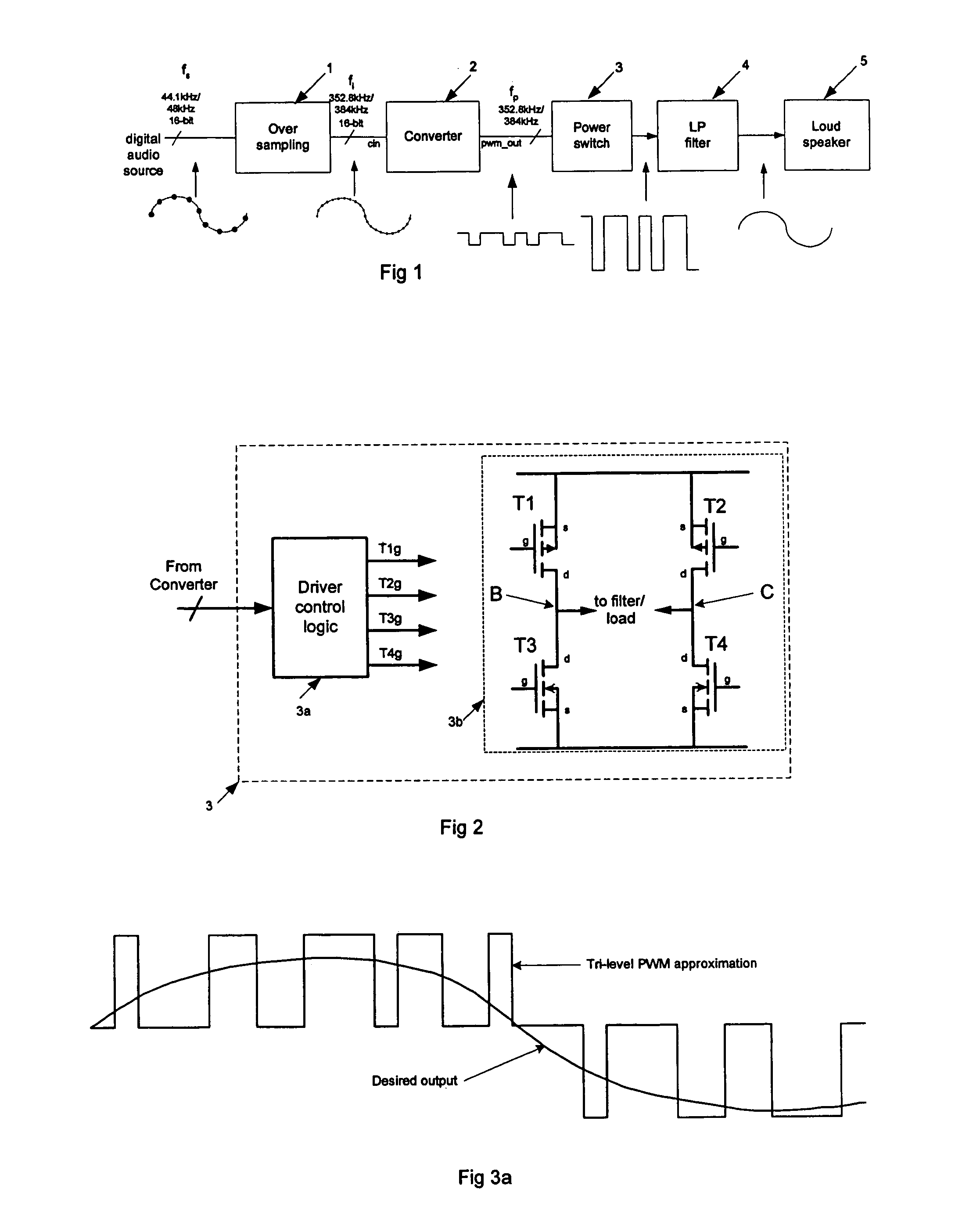
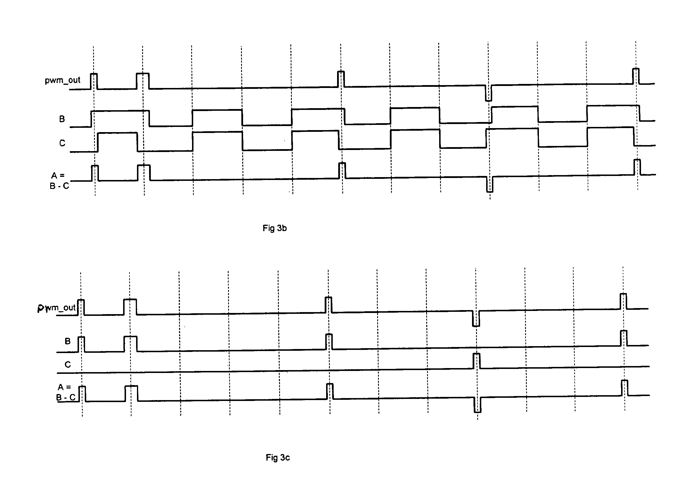
[0021]The modulator then outputs a pulse corresponding to the input signal to the quantiser when this is outside the bounds of the upper and lower thresholds, and output pulses corresponding to the predetermined output(s) of the quantiser when its input signal is between the upper and lower thresholds. Thus the modulator does not output any pulses less than a minimum width unless it is zero, even when only a low (e.g. audio) signal level, between the upper and lower thresholds, is input to the quantiser. In an embodiment the modulator will output pulses of widths corresponding to input signals below the lower threshold and above the upper threshold, or else corresponding to zero, the upper threshold or the lower threshold as appropriate. This avoids the problem of very short output pulses which the output bridge transistors cannot switch quickly enough, thereby reducing the level of distortion.
[0037]By using both half bridges to provide an amplified pulse, the switching times required for the transistors are relaxed, resulting in less distortion and / or lower specification and hence cheaper transistors.

Problems solved by technology

Whilst the modified quantisation does result in extra quantisation error and hence distortion, this is substantially moved out of the audio frequency band in embodiments using noise shaping around the guard-band quantiser.

Method used


Image

  • Pulse width modulator quantisation circuit
  • Pulse width modulator quantisation circuit
  • Pulse width modulator quantisation circuit

Examples


Embodiment Construction

[0056]As discussed previously, the arrangement of FIG. 1 can be used to provide audio output from coded sample values of the original analogue signal. Here pulse width modulation (PWM) techniques are used, in which the sample values are converted into pulses having a width corresponding to the input sample values, and which pulses are used to drive a power switching stage such as illustrated in FIG. 2.

[0057]A PWM converter such as that shown in FIG. 4 is utilised to provide the pulses to drive the switching stage 3. The converter typically utilises a word length reduction circuit 6 coupled to a PWM modulator 7 which provides the actual conversion to pulse width coding.

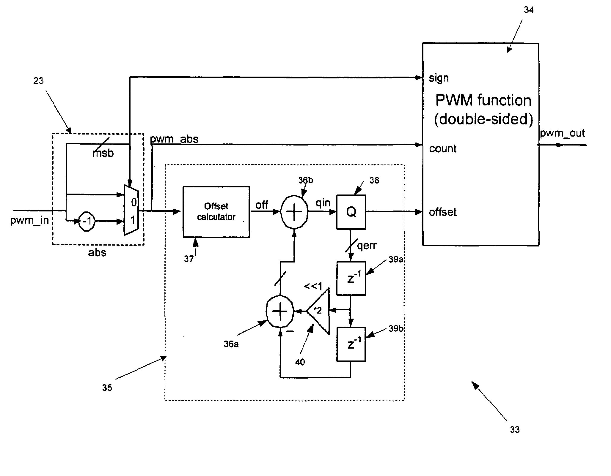
[0058]In one embodiment a modified word length reduction circuit 16 is provided for use with a tri-level PWM modulator 17 as shown in FIG. 5. Here a guard band quantiser QGB 25 is utilised to modify the output characteristics of the word length reduction circuit 16. The word length reduction circuit 16 also comprises a...


PUM


Abstract

The present invention relates to pulse width modulation (PWM) modulators, especially but not exclusively for digital audio applications; and to quantizers and power switching for the same. The present invention provides a pulse width modulation (PWM) modulator or converter having a guard band quantizer arranged to block low level signal inputs to the modulator in order to prevent narrow width output pulses. This arrangement is particularly advantageous when applied to tri-level PWM modulators, but can also be applied to other level PWM modulators such as bi-level for example. Quantization noise can be reduced by implementing the quantizer in a noise shaper circuit (or possibly a SDM) having loop feedback.

Description

FIELD OF THE INVENTION[0001]The present invention relates to pulse width modulation (PWM) modulators, especially but not exclusively for digital audio applications; and to quantisers and power switching for the same.BACKGROUND OF THE INVENTION[0002]Digital amplifiers are typically employed for high efficiency applications for example audio amplification in portable devices such as personal stereos where battery life is a significant consideration. They are also used in high power amplification where the high efficiency means that the size and cost of the power supplies and heat sinks can be reduced. These amplifiers often utilise pulse width modulation (PWM) to drive a switching power stage. However the source signals are typically stored as encoded sampled signals on a carrier such as a CD-ROM or as MP3 tracks on a memory device for example. During playback, these digital encoded signals are error-corrected and decompressed to give a sequence of digital words, each representing the...

Claims


Application Information

Patent Timeline
Patent Type & Authority Patents(United States)
IPC IPC(8): H03M3/00H03M1/82H03M7/32
CPCH03M7/302H03M3/506H03F3/2173H03K7/08H03M1/822H03M5/08
Inventor MAGRATH, ANTHONY J.
Owner CIRRUS LOGIC INC
Why Eureka
Try Eureka