Data transmission method combating degradation of the quality of service

a data transmission and quality technology, applied in the field of transmission methods, can solve the problems of inability to choose any value for np and tp, limited transmission capacity of such a system, and inability to guarantee the quality of servi

Inactive Publication Date: 2007-04-17
APPLE INC
View PDF9 Cites 28 Cited by
  • Summary
  • Abstract
  • Description
  • Claims
  • Application Information

AI Technical Summary

Benefits of technology

[0013]The purpose of the present invention is to remedy the aforementioned drawbacks and in particular to propose a transmission method which guarantees a transmission rate for a

Problems solved by technology

The transmission capacity of such a system is limited by the noise level, the interference between the signals of the different users, the available bandwidth etc.
However, the MAC sub-layer is not able to choose any values for NP and TP.
However, as the transmission powers are limited, it may happen that the resource allocation system cannot guarantee the quality of service

Method used


Image

  • Data transmission method combating degradation of the quality of service
  • Data transmission method combating degradation of the quality of service
  • Data transmission method combating degradation of the quality of service

Examples


first embodiment

[0027]FIG. 3 depicts schematically a transmission method according to the

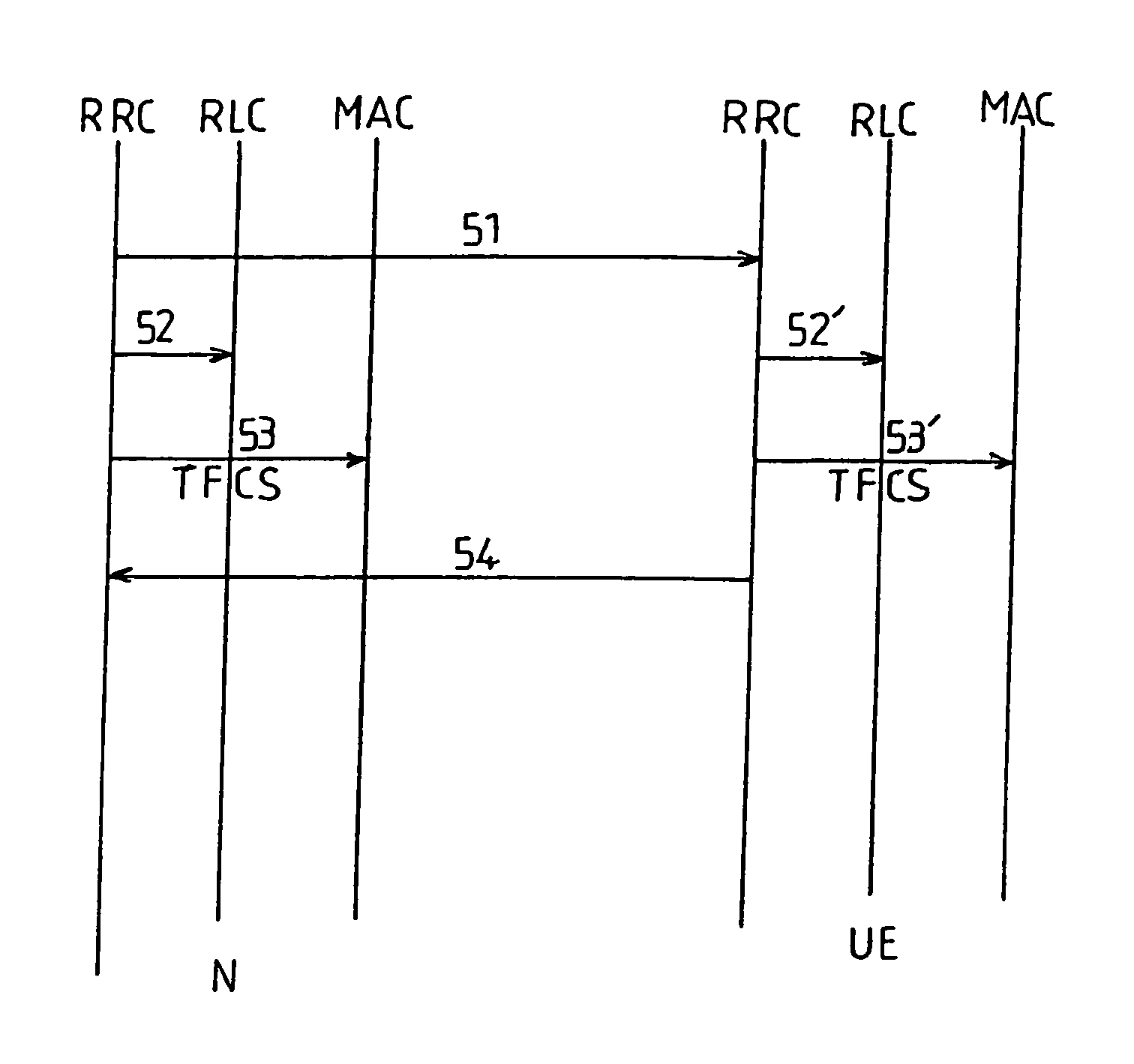
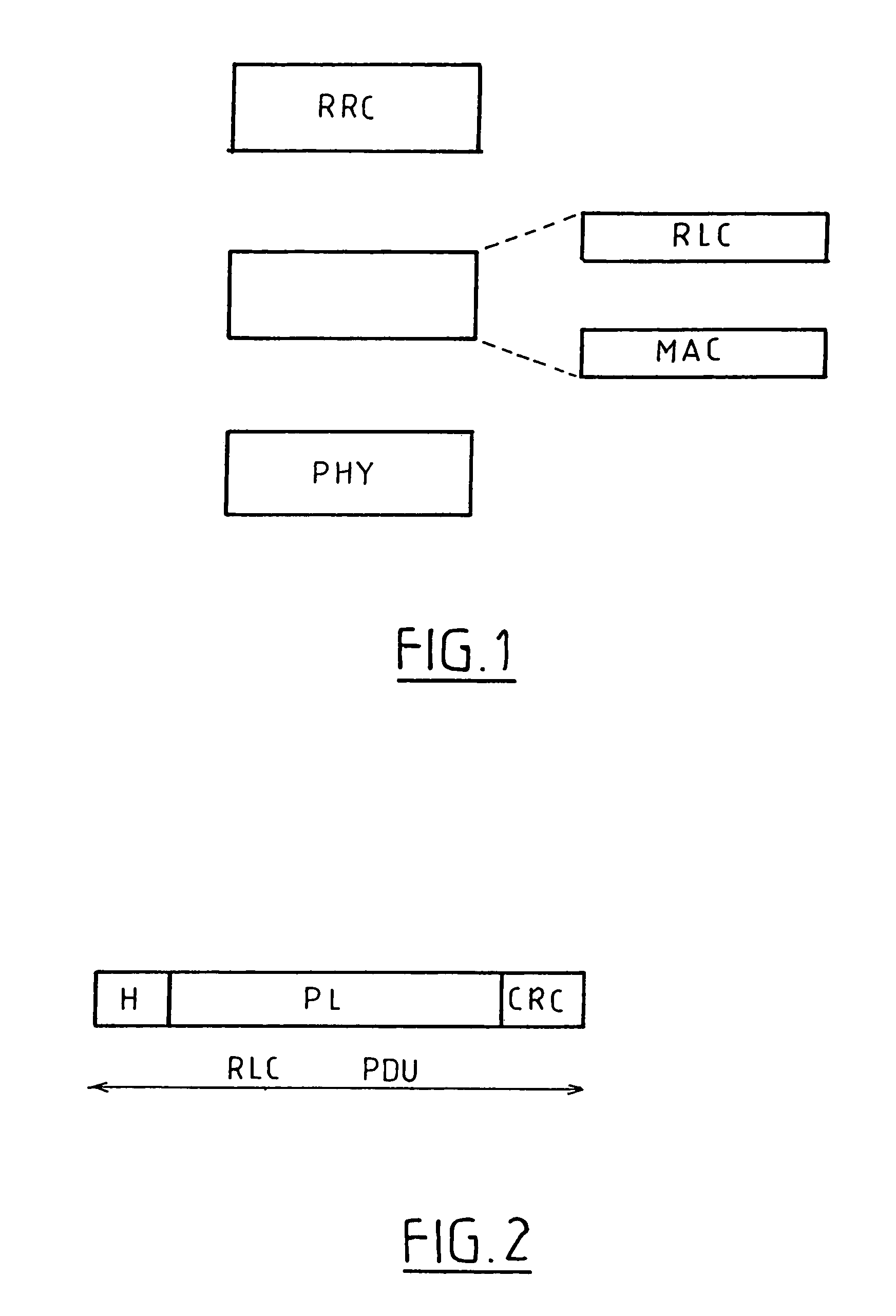
[0028]When a connection is established, the RRC layer supplies to the MAC sub-layer a set of possible sizes for the RLC PDU transmission unit. More precisely, if the mobile telecommunication system is a UMTS system, the RRC layer supplies to the MAC sub-layer on the one hand one TFS (Transport Format Set) table per transport channel and on the other hand a TFCS (Transport Format Combination Set) table relating to all the transport channels which the said sub-layer can use. A TFS table relating to a transport channel consists of a set of pairs (TPj,Nj)j=1 . . . n where TPj is a possible size of the RLC PDU for this channel, Nj is the number of RLC PDUs associated with this size which the MAC sub-layer can transmit in a time interval TTI and n the number of possible pairs on this channel. The TFCS table relates to all the transport channels and comprises a plurality of combinations TFCi of possible transport form...

second embodiment

[0034]FIG. 4 depicts schematically a transmission method according to a

[0035]According to this embodiment, the size of the RLC PDU is fixed at the start of connection by the RRC layer. The RLC and MAC sub-layers are then configured according to this size.

[0036]Unlike the first embodiment, the RLC sub-layer functions with only one size of PDU. The procedure of changing the size of the RLC PDU requires the action of the RRC layer of the network, whether this is functioning as a transmitter or as a receiver.

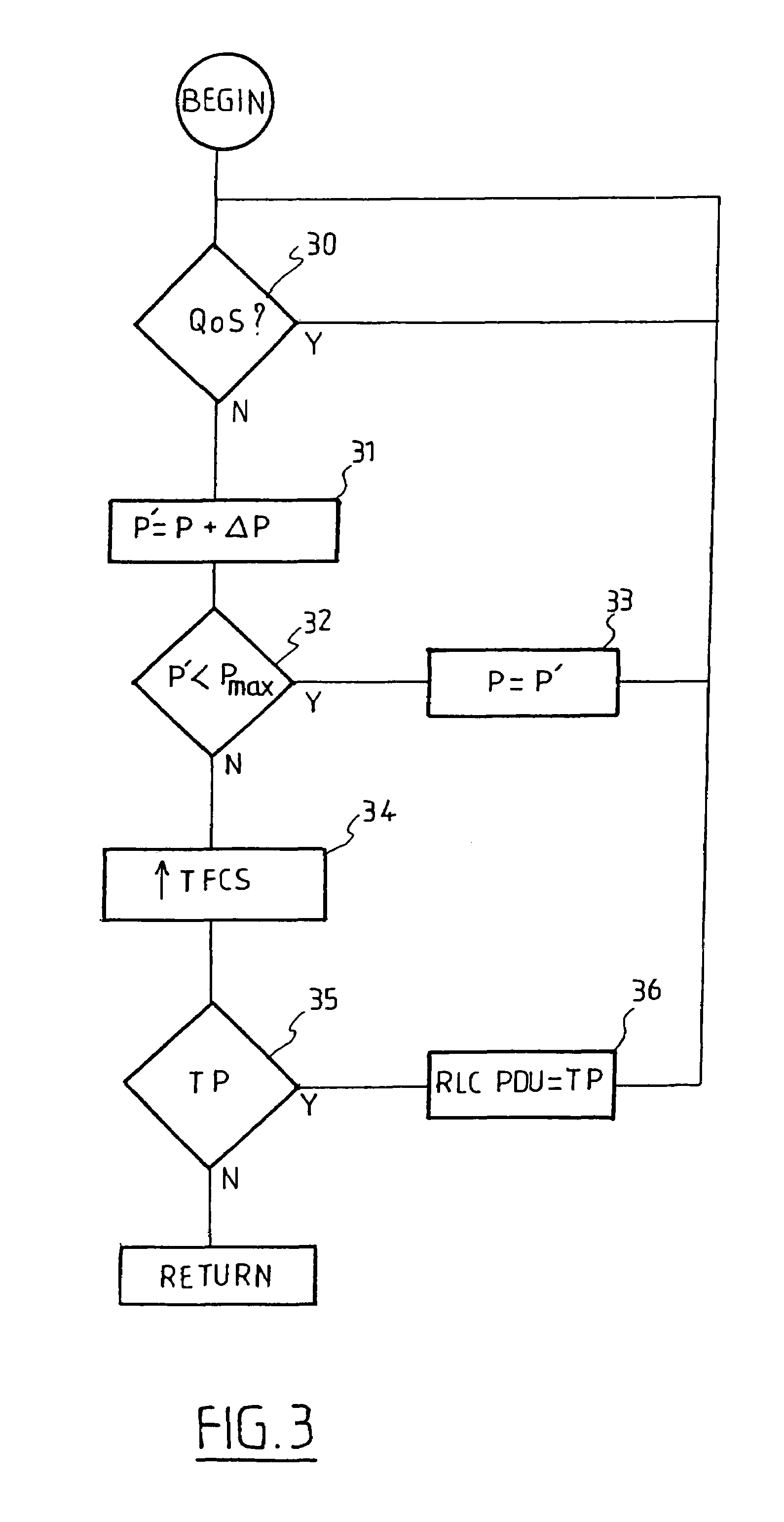
[0037]Firstly (40), the network checks whether the quality of service (QoS) required is indeed complied with by comparing the error rate per RLC PDU with a threshold value. If the network is functioning as a transmitter, the error rate will be supplied as before by the status reports sent by the receiver. If the network is functioning as a receiver, the error rate will be supplied by the RLC sub-layer of the network. Alternatively, compliance with the quality of service is verified ...


PUM


Abstract

A system for transmitting data over a physical resource including a layer configured to manage the physical resource and to guarantee a quality of service, and a first sub-layer configured to supply a transmission support in accordance with the quality of service and to segment the data into transmission units. The first sub-layer reduces a size of at least one of the transmission units when transmission conditions on the physical resource are degraded. A second sub-layer is configured to transmit at least one of the transmission units over the physical resource during each of transmission time intervals. The transmission time interval is a periodic time interval during which the second sub-layer is allowed to access the physical resource. A physical layer is configured to perform error correction coding or decoding of the data.

Description

BACKGROUND OF THE INVENTION[0001]The present invention concerns in general terms a method of transmitting data over a physical resource. More precisely the present invention concerns a transmission method combating the degradation of the quality of service in a mobile telecommunications system.[0002]Such a system consists of one or more receivers connected to one or more transmitters by radio links. The transmission capacity of such a system is limited by the noise level, the interference between the signals of the different users, the available bandwidth etc. It must therefore be shared between the different users according to a resource allocation process enabling each user to have available as far as possible the services which he has requested.[0003]For this purpose, a mobile telecommunication system uses three protocol layers as depicted in FIG. 1.[0004]The upper layer or RRC (Radio Resource Control) layer is responsible for managing the whole of the physical resource and guara...

Claims


Application Information

Patent Timeline
IPC IPC(8): H04Q7/00H04L1/00H04L47/36H04W52/04
CPCH04L1/0007H04L1/0025H04L1/0029H04L29/06H04L47/10H04L47/36H04W52/04H04L69/32H04L69/324H04L9/40
Inventor SEGUIN, LAURE
Owner APPLE INC
Why Eureka
Try Eureka