
X-ray analysis apparatus

a technology of x-ray analysis and apparatus, which is applied in the direction of material analysis using radiation diffraction, instruments, measurement devices, etc., can solve the problems of inability to perform x-ray measurement under optimal conditions, time consumed in the measurement, and inability to accurately determine the effect of the measuremen

Inactive Publication Date: 2007-04-17
RIGAKU CORP
View PDF8 Cites 13 Cited by
  • Summary
  • Abstract
  • Description
  • Claims
  • Application Information

AI Technical Summary

Benefits of technology

The present invention provides an X-ray analysis apparatus that can quickly and accurately perform X-ray measurements by allowing the X-ray detecting means to perform scanning operation of the X-ray detecting means. The apparatus includes an X-ray radiation means for irradiating a sample with X-ray, an X-ray detecting means for detecting X-ray emission from the sample, and an image control means for displaying information related to X-ray intensity and the scanning angle of the X-ray detecting means simultaneously with the scanning operation. The apparatus can provide more various kinds of X-ray information compared to conventional X-ray analysis apparatuses, and the operator can determine whether the used sample is adequate or not, or whether measurement condition is adequate or not within a short span of time after the start of the measurement.

Problems solved by technology

In general, the X-ray measurement performed by the X-ray analysis apparatus is time consuming.
The X-ray measurement is not always performed under the optimal condition.
Thus, in the case where the sample itself or measurement condition is not adequate, the time engaged in the measurement comes to nothing.

Method used


Image

  • X-ray analysis apparatus
  • X-ray analysis apparatus
  • X-ray analysis apparatus

Examples


Embodiment Construction

[0030]An embodiment of the present invention will be described below. In this embodiment, the present invention is applied to an X-ray diffractometer using a θ-2θ system goniometer. It goes without saying that the present invention is not limited to the following embodiment.

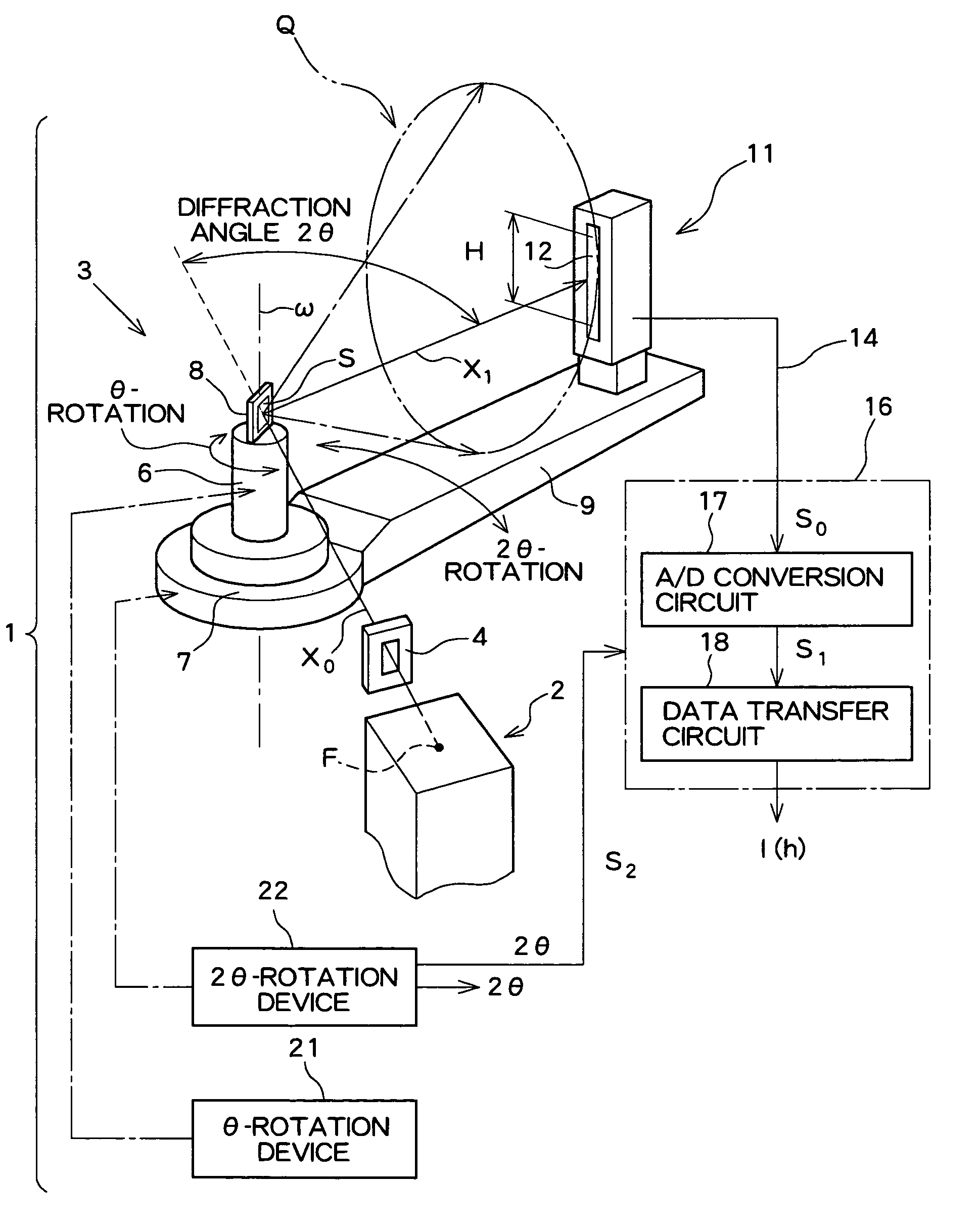
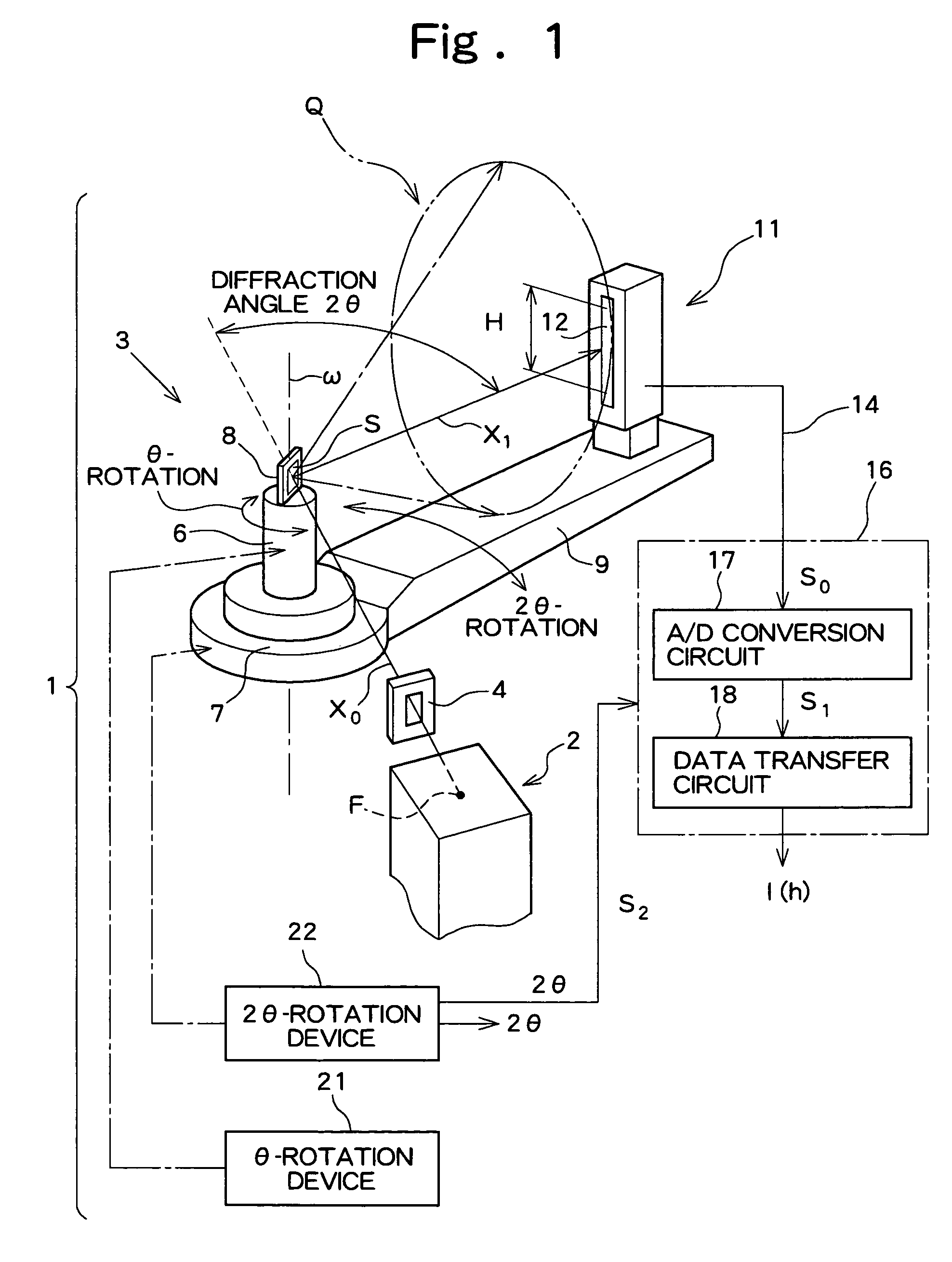
[0031]FIG. 1 shows a mechanical configuration of an X-ray diffractometer according to the embodiment of the present invention. An X-ray diffractometer 1 shown in FIG. 1 includes an X-ray generator 2 and a goniometer 3, that is, an angle-measuring device. The X-ray generator 2 has an X-ray source “F”.

[0032]A divergence-limiting slit 4 is provided between the X-ray generator 2 and the goniometer 3. The slit 4 controls the divergence of X-ray so that the X-ray is focused on a sample “S”. The goniometer 3 has a θ-rotation table 6 and a 2θ-rotation table 7 situated under the θ-rotation table 6. The θ-rotation table 6 and 2θ-rotation table 7 has the same rotation axis. A sample holder 8 is fitted to the upper surface o...


PUM

PropertyMeasurementUnit
aaaaaaaaaa
aaaaaaaaaa
angleaaaaaaaaaa

Abstract

An X-ray analysis apparatus includes: an X-ray radiation unit that irradiates a sample with X-ray; an X-ray detection unit that detects X-ray emission from the sample; a unit that allows the X-ray detection unit to perform scanning operation for changing the angle of the X-ray detection unit with respect to the sample; and an image controller that displays information related to X-ray intensity detected by the X-ray detection unit and information related to a scanning angle of the X-ray detection unit as a 3D image. The image controller displays the 3D image simultaneously with the scanning operation of the X-ray detection unit. Further, simultaneously with the scanning operation of the X-ray detection unit, two or all of 1D, 2D, and 3D images are displayed in one screen. A measurement result starts being displayed as a 3D image before information related to all measurement results has been obtained.

Description

BACKGROUND OF THE INVENTION[0001]1. Field of the Invention[0002]The present invention relates to an X-ray analysis apparatus that analyzes a sample using X-ray.[0003]2. Description of the Related Art[0004]At present, various X-ray analysis apparatuses such as an X-ray diffractometer, an X-ray small angle measurement apparatus, and a fluorescent X-ray analysis apparatus are known. The above X-ray analysis apparatuses irradiate a sample with X-ray and detect X-ray radiation (diffracted radiation, scattered radiation, fluorescent X-ray, or the like) from the sample using an X-ray detector. More specifically, the central line of X-ray incident on the sample, or so-called incident X-ray optical axis is set at 0°. The analyzers then detect the angle of the X-ray radiation with respect to the incident X-ray optical axis and the intensity of the radiation, thereby determining physicality of the sample.[0005]To observe the angle of the X-ray radiation with respect to the incident X-ray optic...

Claims


Application Information

Patent Timeline
Patent Type & Authority Patents(United States)
IPC IPC(8): G01N23/20H05G1/28G01N23/223G01T1/36G01N23/207
CPCG01N23/20016
Inventor OBATA, YASUSHIKAKEFUDA, KOHJI
Owner RIGAKU CORP
Learn More