System and related methods for signaling the position of a movable barrier and securing its position

a technology of movable barriers and signaling methods, which is applied in the direction of door/window fittings, instruments, constructions, etc., can solve the problems of manual setting of up and down limits, inability to detect the position of movable barriers, and inability to adjust the position of switches

Inactive Publication Date: 2007-04-24
GMI HLDG
View PDF32 Cites 71 Cited by
  • Summary
  • Abstract
  • Description
  • Claims
  • Application Information

AI Technical Summary

Problems solved by technology

But these switches have a limited life span.
Metal fatigue and corrosion are the most likely causes of switch failure.
Another drawback of mechanical switches is that they can be wired in series with the motor which creates high current draw across the contacts of the switch causing the contacts to fail.
A further limitation of limit switches is that the up and down limits, which must be set manually, can be improperly set or misadjusted.
Unfortunately, pulse counters cannot accurately keep count.
External factors such as power transients, electrical motor noise, and radio interference often disrupt the count allowing the door to over-travel or under-travel.
The microprocessor may also lose count if power to the operator is lost or if the consumer manually moves the door while the power is off and the door is placed in a new position which does not match the original count.
Such a system cannot indicate where the door is, if the door is neither fully open nor fully closed.
These devices also are limited to the indication of either the door being closed or not closed.
But, as noted, these pulse-counting devices can lose count or need to be reset any time power is lost.
For example, if a door is closed and power is lost, when the power comes on the operator does not know if the door is open or closed until the motor is started and the door either stalls or begins to move.
However, the audiovisual device provides no specific indication of door position as the door moves.
However, no external output for indicating door position, via the potentiometer, is made.
However, no discussion is provided of a device that blocks an actuation signal to prevent door movement.
However, no intermediate positions of the door are provided by the indicator.
Nothing in this patent discloses that the receiver may receive a blocking signal to disable operation of the door.

Method used


Image

  • System and related methods for signaling the position of a movable barrier and securing its position
  • System and related methods for signaling the position of a movable barrier and securing its position
  • System and related methods for signaling the position of a movable barrier and securing its position

Examples


Embodiment Construction

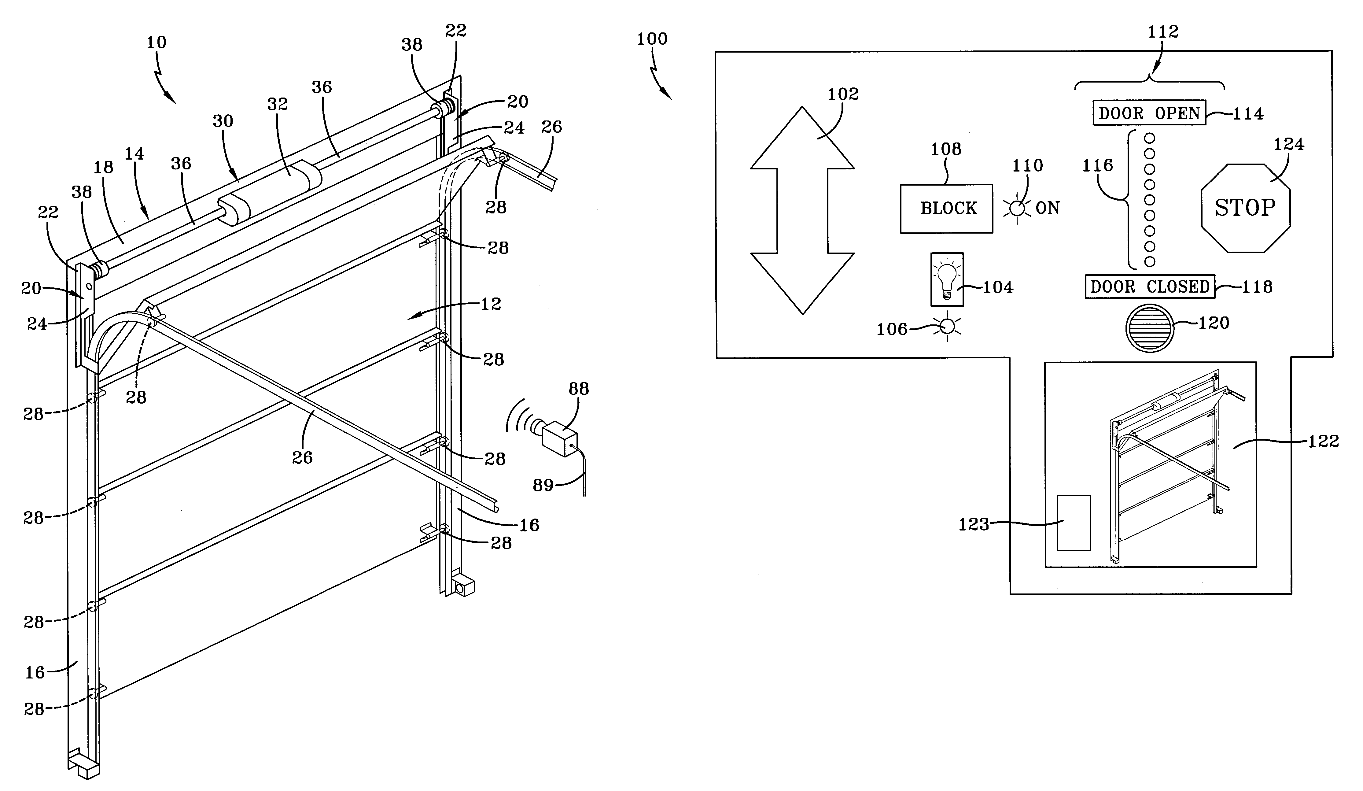
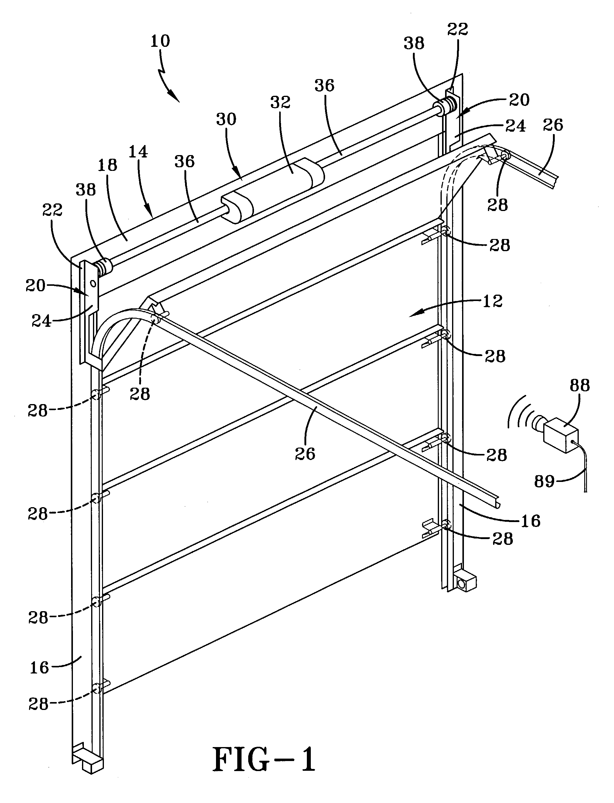
[0024]A system and related methods for signaling the position of a movable barrier and securing its position is generally indicated by the numeral 10 in FIG. 1 of the drawings. The system 10 is employed in conjunction with a movable barrier such as a conventional sectional garage door generally indicated by the numeral 12. But, the movable barrier may also be in the form of a gate, curtain, awning, rollable shutter or the like. The opening in which the door is positioned for opening and closing movements relative thereto is surrounded by a frame, generally indicated by the numeral 14, which consists of a pair of vertically spaced jamb members 16 that, as seen in FIG. 1, are generally parallel and extend vertically upwardly from the ground (not shown). The jambs 16 are spaced and joined at their vertically upper extremity by a header 18 to thereby form a generally u-shaped frame 14 around the opening for the door 12. The frame 14 is normally constructed of lumber or other structural ...


PUM


Abstract

A system for signaling the position of a movable barrier includes a movable barrier; a motor coupled to the movable barrier for moving the movable barrier between limit positions; a position detection device that monitors the movable barrier to generate a barrier position signal; and an indication device that receives the barrier position signal and indicate a position of the movable barrier relative to the limit positions. The system also includes an operation mechanism for controlling the motor and at least one transmitter device which generates a transmission signal received by the operator mechanism to energize the motor. The system further includes a blocking switch which generates a blocking signal received by the operator mechanism to prevent receipt of a transmission signal from a device other than one associated with the indication device.

Description

TECHNICAL FIELD[0001]Generally, the present invention relates to detecting the position of a movable barrier, such as a garage door, as it travels between open and closed positions. More particularly, the present invention relates to a system which obtains and continually represents the positional status of the movable barrier. More specifically, the present invention relates to a system which employs a device to detect a position of the movable barrier and uses either a visual or audio representation to indicate the position of the barrier. And the system includes a feature that blocks wireless signals when it is desired to disable movement of the barrier.BACKGROUND ART[0002]As is well known, motorized garage door operators automatically open and close a garage door through a path that is defined by an upper limit and a lower limit wherein the limits can be identified electrically or mechanically. The lower limit is established by the floor upon which the garage door closes. The up...

Claims


Application Information

Patent Timeline
Patent Type & Authority Patents(United States)
IPC IPC(8): E05F11/00E05F15/16E05F15/20
CPCE05F15/77E05F15/668E05Y2400/80E05Y2800/426E05F15/00E05Y2900/106
Inventor MULLET, WILLIS J.
Owner GMI HLDG
Why Eureka
Try Eureka