
Paper insertion limiting device for a paper feeding unit

a technology of limiting device and paper feeding unit, which is applied in the direction of thin material processing, article separation, printing, etc., can solve the problems of high manufacturing cost, noise generation, and above the limiting device of paper feeding unit, and achieve the effect of reducing manufacturing cost and simplifying structur

Inactive Publication Date: 2007-04-24
S PRINTING SOLUTION CO LTD
View PDF7 Cites 6 Cited by
  • Summary
  • Abstract
  • Description
  • Claims
  • Application Information

AI Technical Summary

Benefits of technology

[0016]A first aspect of the present invention provides a paper insertion limiting device of a paper feeding unit having a simplified structure thereby being less costly.
[0037]Accordingly, with the paper insertion limiting device of a paper feeding unit according to the present invention as above, the manufacturing costs can be lowered due to the simplified structure.
[0038]Further, the present invention can provide the paper insertion limiting device of a paper feeding unit having no noise and the same pickup condition at all times.
[0039]Further, the present invention can provide the paper insertion limiting device of a paper feeding unit having no need to additionally control a motor to load papers.

Problems solved by technology

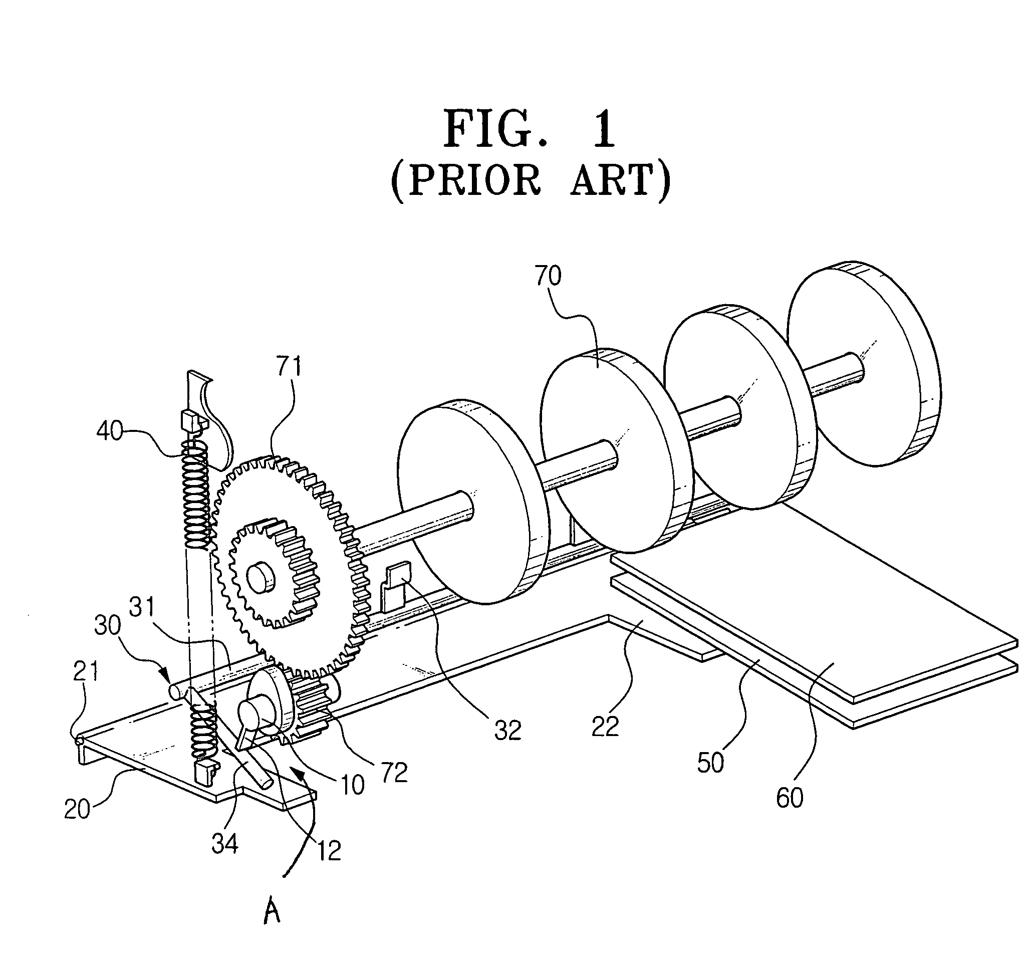
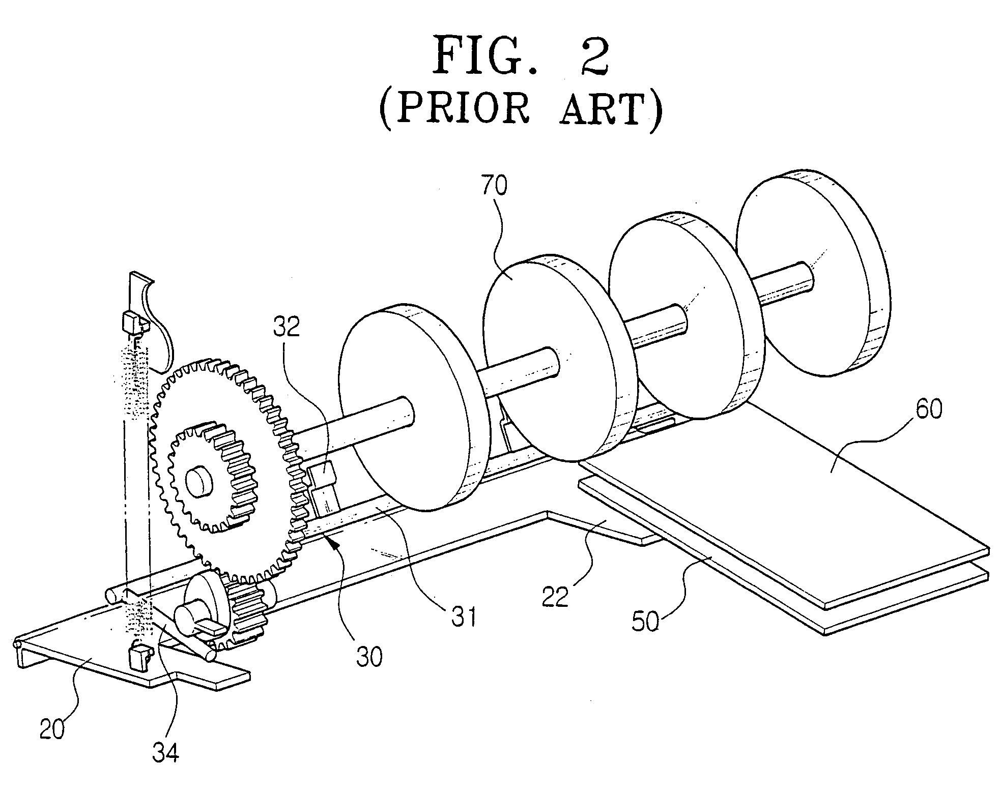
However, the above paper insertion limiting device of a paper feed unit has various problems as follows.
First, since such paper insertion limiting device has a complicated structure and lots of parts, the manufacturing costs are high.
Second, noise is produced since the elevating plate repeats its ascent and descent operations every time a paper is picked up.
Fourth, the reliability on paper pickup operations is degraded since the paper pickup condition is not the same all the time.

Method used


Image

  • Paper insertion limiting device for a paper feeding unit
  • Paper insertion limiting device for a paper feeding unit
  • Paper insertion limiting device for a paper feeding unit

Examples


first embodiment

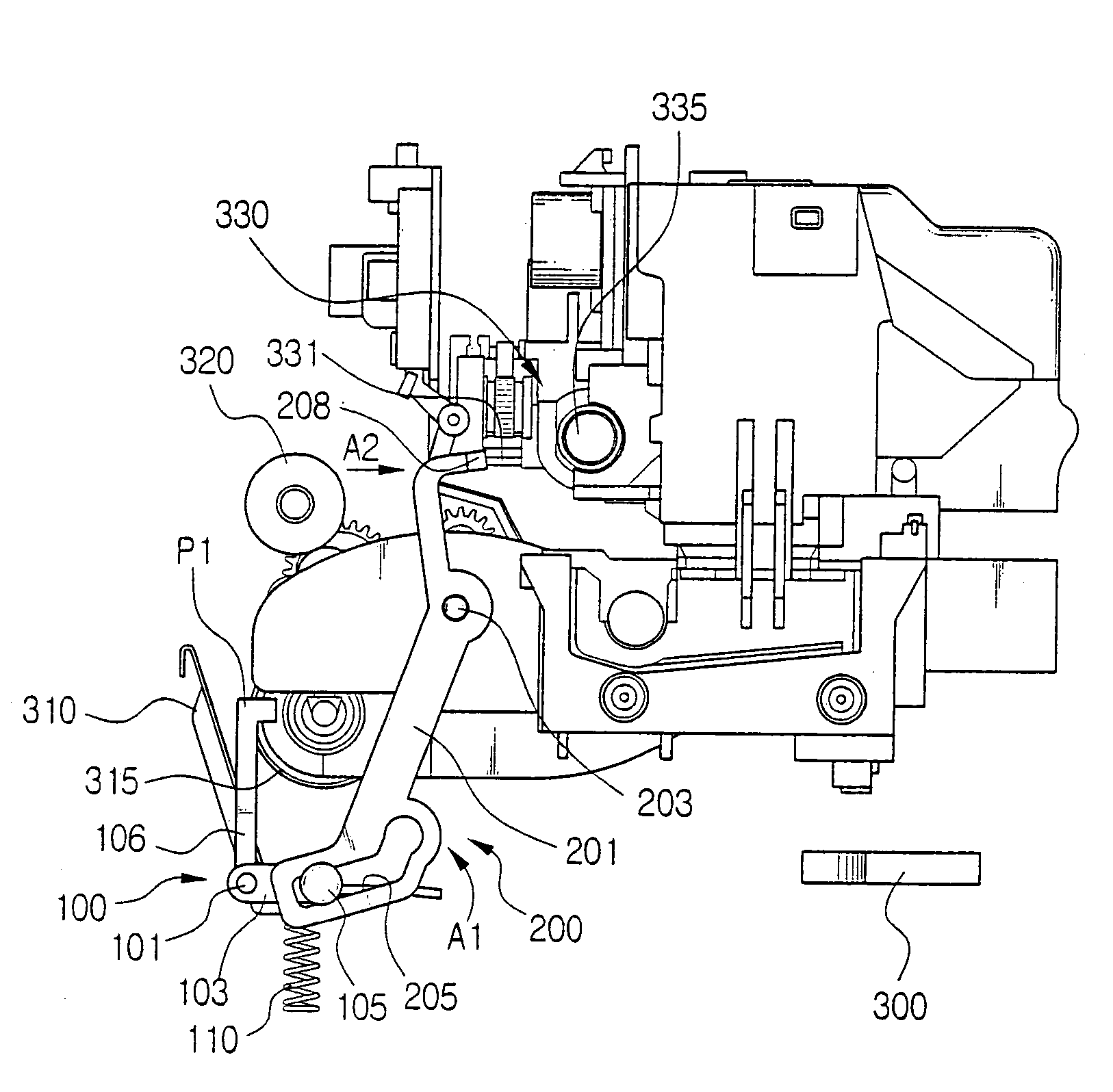
[0063]Hereinafter, the operations of the paper insertion limiting device of the paper feeding unit as above according to the present invention will be described with reference to FIG. 3 to FIG. 6 out of the accompanying drawings.

[0064]First, when papers are loaded into the paper feeding unit 300 of an inkjet printer, the carrier 330 moves to the home position. When the carrier 330 reaches the home position, the actuating piece 331 pushes the cam 208 of the regulating member activator 200 to the left direction as shown by an arrow A4 (FIG. 6). When the cam 208 is pushed to the left, the regulating member activator 200 rotates in the counterclockwise direction about the pivot 203. When the regulating member activator 200 rotates to the counterclockwise direction, the guide pin 105 of the sheet regulating member 100 inserted in the guide slit 205 is pressed down as shown by an arrow A3 (FIG. 6). When the guide pin 105 is pressed down by the guide slit 205, the spring 110 positioned und...

second embodiment

[0067]Further, FIG. 7 is a view to show a paper insertion limiting device of a paper feeding unit according to the present invention.

[0068]In FIG. 7, the paper insertion limiting device of a paper feeding unit according to the second embodiment includes a sheet regulating member 100′ and the regulating member activator 200.

[0069]The sheet regulating member 100′ is to prevent the papers (not shown) loaded in the paper feeding unit 300 from being inserted to the drive roller 320 (FIG. 6), which has the lever shaft 101, lever arm 103, and paper wall 150.

[0070]The lever shaft 101 is rotatably mounted to the front end of the paper feeding unit 300, and the lever arm 103 is installed to be protruded on one end of the lever arm 103. The lever arm 103 is activated by the regulating member activator 200, and activates the lever shaft 101 to rotate in a certain angle range. A guide pin 105 is formed on the front end of the lever arm 103, and engaged in the guide slit 205 formed on the one end...

third embodiment

[0078]Further, FIG. 9A is a view to show a paper insertion limiting device of a paper feeding unit according to the present invention, omitting the paper feeding unit, carrier, drive roller, and the like.

[0079]The paper insertion limiting device of a paper feeding unit according to the third embodiment includes a first link 210, a second link 220, and a sheet regulating member 130.

[0080]The first link 210 has a cam 211 on one end thereof to convert the liner movements of the carrier 330 to linear movements in a direction perpendicular to the movement direction of the carrier 330 (refer to FIG. 9B to observe a cam shape, showing a plan view of the cam in circle A of FIG. 9A). A first guide pin 213 is formed on the other end of the first link 210. The second link 220 converts the linear movements of the first link 210 into rotational movements, which is mounted by a pivot 225 on the printer main body. First and second guide grooves 221 and 223 are formed on both ends of the second lin...


PUM


Abstract

A paper insertion limiting device of a paper feeding unit which prevents papers from being inserted to a drive roller when the papers are loaded. The paper insertion limiting device of a paper feeding unit is provided with a sheet regulating member mounted on the front end of the paper feeding unit to rotate by a certain angle, and regulate an insertion depth of papers loaded in the paper feeding unit, and a regulating member activator to actuate the sheet regulating member to block the front ends of papers when the carrier reaches a certain position, and to feed papers when the carrier moves out of the certain position. The sheet regulating member forms a right angle to the face of papers when the carrier reaches the certain position, and the paper regulation member forms an obtuse angle to the papers when the carrier moves out of the certain position.

Description

CROSS-REFERENCE TO RELATED APPLICATIONS[0001]This application claims the benefit of Korean Application No. 2002-86852, filed Dec. 30, 2002, in the Korean Intellectual Property Office, the disclosure of which is incorporated herein by reference.BACKGROUND OF THE INVENTION[0002]1. Field of the Invention[0003]The present invention relates to a paper feeding unit of a printer or a multi-function machine, and more particularly, to a paper insertion limiting device of a paper feeding unit which evenly aligns the front ends of papers when the papers are loaded in the paper feeding unit.[0004]2. Description of the Related Art[0005]In general, an automatic sheet feeder (ASF) is mainly employed in a paper feeding unit in an inkjet printer or a multi-function machine. The ASF is provided with a paper insertion limiting device preventing the front ends of papers from being further inserted beyond a certain position since the papers may come out of the certain position and be inserted into a dri...

Claims


Application Information

Patent Timeline
IPC IPC(8): B41J13/26B41J13/00B41J13/10B65H1/14B65H3/06B65H9/06
CPCB41J13/0018B41J13/103B65H1/14B65H3/0669B65H3/50B41J13/00
Inventor JANG, DEOK-HWAN
Owner S PRINTING SOLUTION CO LTD
Learn More