Transmission for power take-off

a technology for power take-off and transmission, applied in the direction of fluid gearing, transportation and packaging, gearing, etc., to achieve the effect of less cost and compact assembly

Active Publication Date: 2007-04-24
DEERE & CO
View PDF10 Cites 32 Cited by
  • Summary
  • Abstract
  • Description
  • Claims
  • Application Information

AI Technical Summary

Benefits of technology

[0006]Accordingly, an object of this invention is to provide a compact transmission which maintains a constant PTO speed despite variations in engine speed.
[0008]A one-way clutch is also coupled by gears to the planetary sun gear. The one-way clutch is free to rotate in only one direction, but locks up and will not rotate in the opposite direction. This prevents rotation of the sun gear in a corresponding direction so that all power is transmitted mechanically. The addition of the one-way clutch results in a less costly and more compact assembly because a smaller hydraulic motor may be used.

Problems solved by technology

However, this requires a larger motor with a large torque capacity in order to prevent rotation of the sun gear in this situation.

Method used


Image

  • Transmission for power take-off
  • Transmission for power take-off

Examples


Embodiment Construction

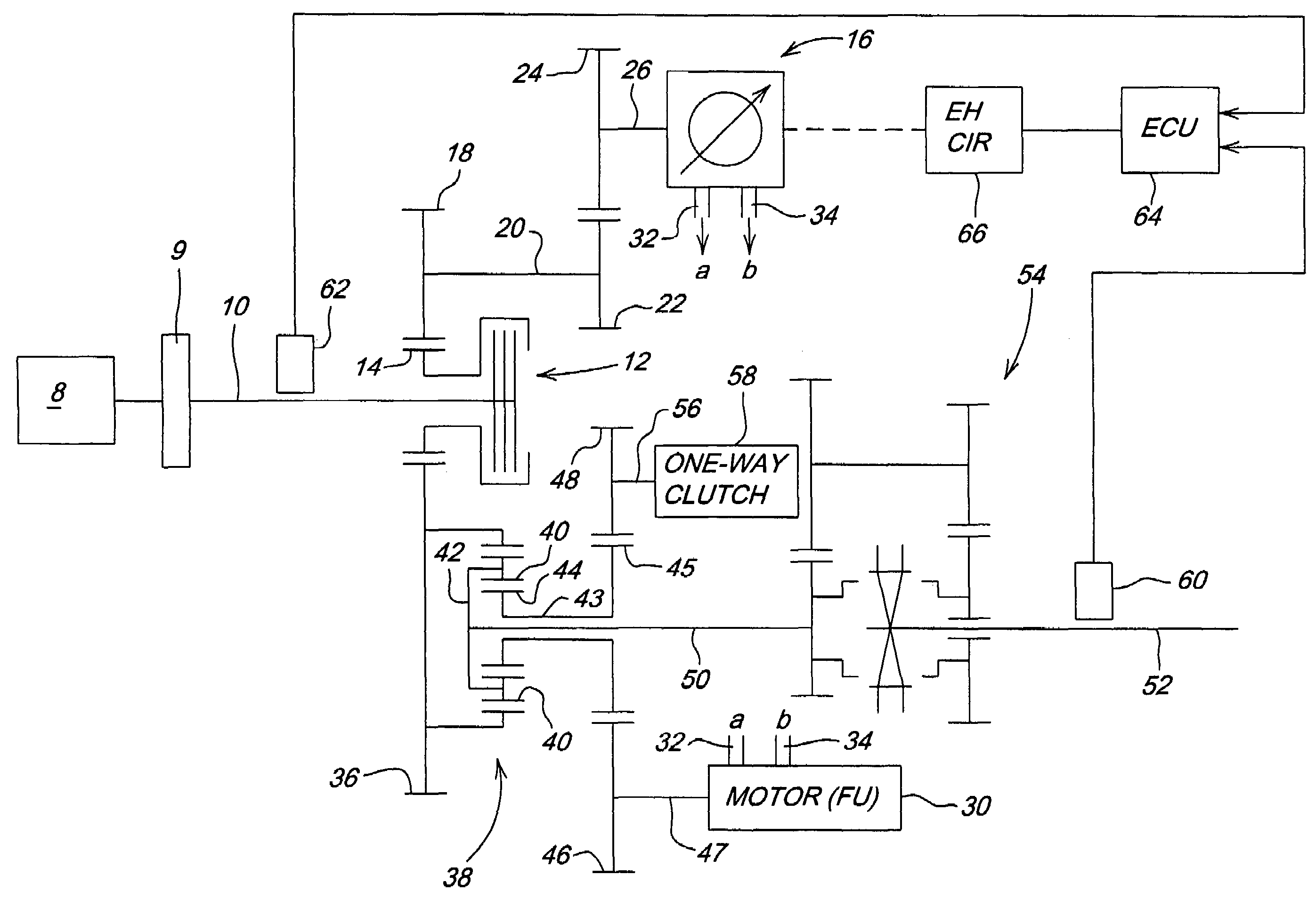
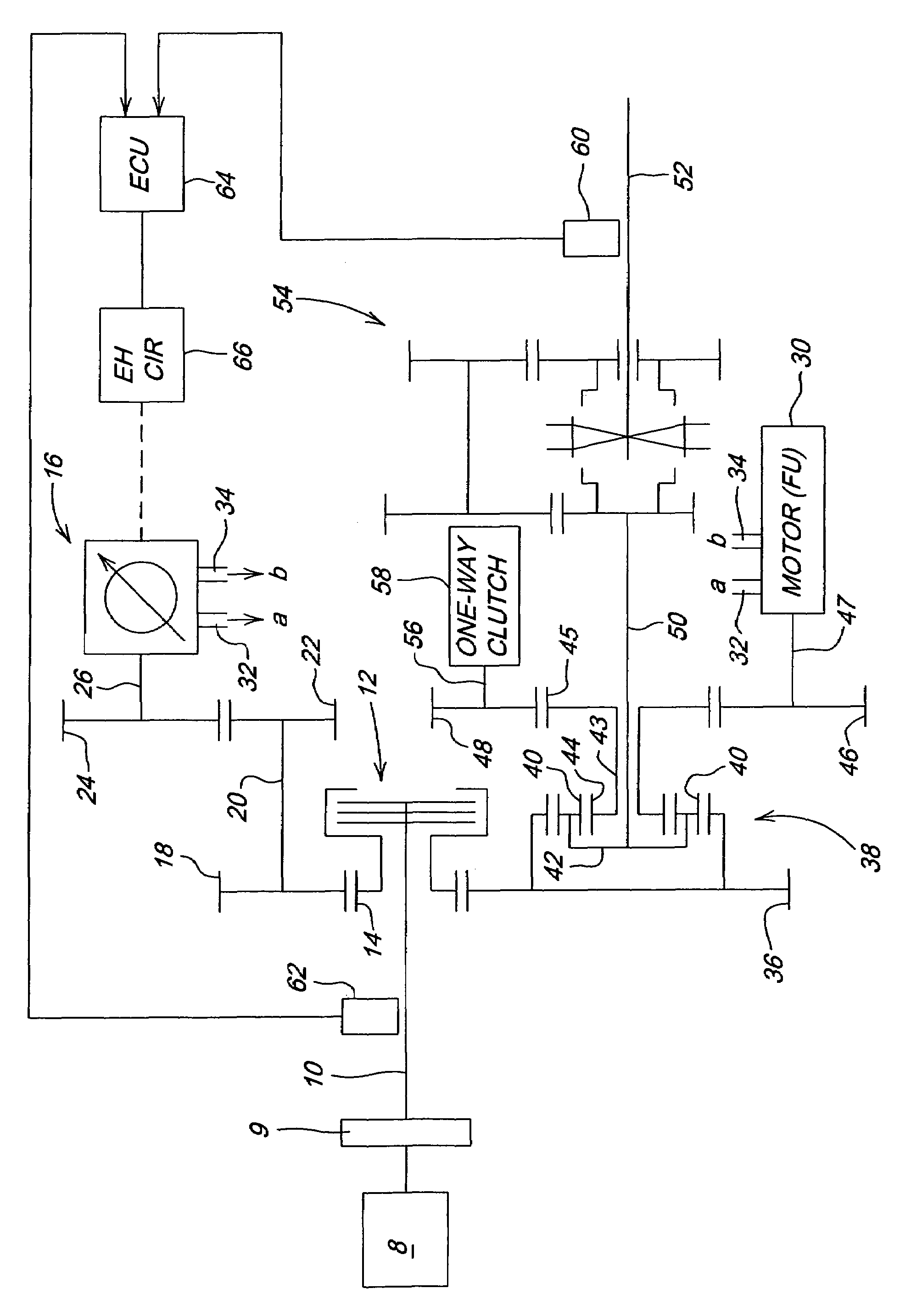
[0010]Referring now to FIG. 1, engine 8 drives shaft 10 (which rotates counter-clockwise when viewed from the rear or right with respect to FIG. 1) via a speed reduction gear unit 9. Shaft 10 drives a PTO transmission clutch 12, which drives a PTO clutch gear 14. Clutch gear 14 drives a variable displacement hydraulic pump 16 via gear 18, shaft 20 gears 22, 24 and shaft 26. Pump 16 circulates hydraulic fluid to a fixed displacement motor 30 via hydraulic lines 32 and 34. Pump 16 and motor 30 comprise a variable speed unit.

[0011]Clutch gear 14 also drives a ring gear 36 of planetary transmission unit 38 which includes planet gears 40 coupled to the ring gear 36 and rotatably mounted on planet carrier 42. The planetary unit also includes a smaller sun gear 44 non-rotatably mounted on an end of a hollow shaft 43 and coupled to the planet gears 40. A larger sun gear 45 is non-rotatably mounted on the other end of shaft 43 and is coupled to a motor gear 46 and to a one-way clutch gear 48...


PUM


Abstract

A PTO transmission transmits power from an engine-driven shaft to a PTO shaft. The transmission includes a variable displacement hydraulic pump driven by the engine-driven shaft. A planetary transmission unit includes a ring gear driven by the engine-driven shaft, a planet carrier drivingly coupled to the PTO shaft, planet gears rotatably mounted on the planet carrier and in meshing engagement with the ring gear, and a sun gear in meshing engagement with the planet gears and drivingly connected to a fixed displacement variable speed hydraulic motor hydraulically driven by the pump. A one-way clutch is coupled to the sun gear. The one-way clutch allows the sun gear to rotate in only one direction so that at rated engine speed all power is transmitted mechanically.

Description

BACKGROUND OF THE INVENTION[0001]The present invention relates to a mechanism for transmitting power from an engine shaft to a power take-off (PTO) shaft.[0002]A PTO transmission system with a planetary gear split power transmission unit is described in U.S. Pat. No. 6,692,395, issued on 17 Feb. 2004 and assigned to the assignee of this application. With this system, power can be transmitted from an engine to a PTO shaft, and the PTO shaft speed can be maintained constant regardless of variations in engine speed.[0003]This transmission has an output connected to a PTO shaft, a first input connected to an engine output shaft and a second input connected to an output of a fixed displacement hydraulic motor. The motor is driven by a variable displacement hydrostatic pump which is driven by the engine output shaft. A control unit controls the speed of the variable speed drive unit as a function of sensed engine speed and to maintain the PTO shaft at a constant speed.[0004]This system tr...

Claims


Application Information

Patent Timeline
Patent Type & Authority Patents(United States)
IPC IPC(8): F16H47/04
CPCB60K17/28F16H47/04F16H2037/0886F16H2200/2005
Inventor RODEGHIERO, RENO ANTONIOSTETTLER, WERNERKLABUNDE, BARBARANIEBERGALL, JAMES ALBERT
Owner DEERE & CO
Why Eureka
Try Eureka