Line illuminating device

a technology of illuminating light and line, which is applied in the direction of solid-state devices, instruments, material analysis, etc., can solve the problems of uneven reading image, limit to providing uniform distribution of light intensity of illuminating light, etc., and achieve the effect of clear reading

Inactive Publication Date: 2007-04-24
NIPPON SHEET GLASS CO LTD
View PDF24 Cites 27 Cited by
  • Summary
  • Abstract
  • Description
  • Claims
  • Application Information

AI Technical Summary

Benefits of technology

[0037]Since at least a part of the outside surface of the light guide casing is provided with a coating film for controlling scattering and reflection of the light or is covered by the member for controlling scattering and reflection of the light, it is possible to prevent the light scattered and reflected from the document surface from being scattered and reflected again at the light guide casing. With this, irradiation by the light scattered and reflected at the light guide casing on the document surface is eliminated. Accordingly, the original intensity distribution of the illuminating light is not disturbed by the scattered and reflected light from the light guide casing and as a result, an image can be clearly read.

Problems solved by technology

In a conventional line illuminating device using a light guide, there is a limit to providing a uniform distribution of light intensity of illuminating light.
Further, there is some possibility in the conventional line illuminating device that shading is produced when there is a fold, laminating difference in level, or the like on the surface of a document paper Still further, in the conventional line illuminating device, there is a possibility that unevenness in the reading image is caused when the document is elevated.

Method used


Image

  • Line illuminating device
  • Line illuminating device
  • Line illuminating device

Examples


first embodiment

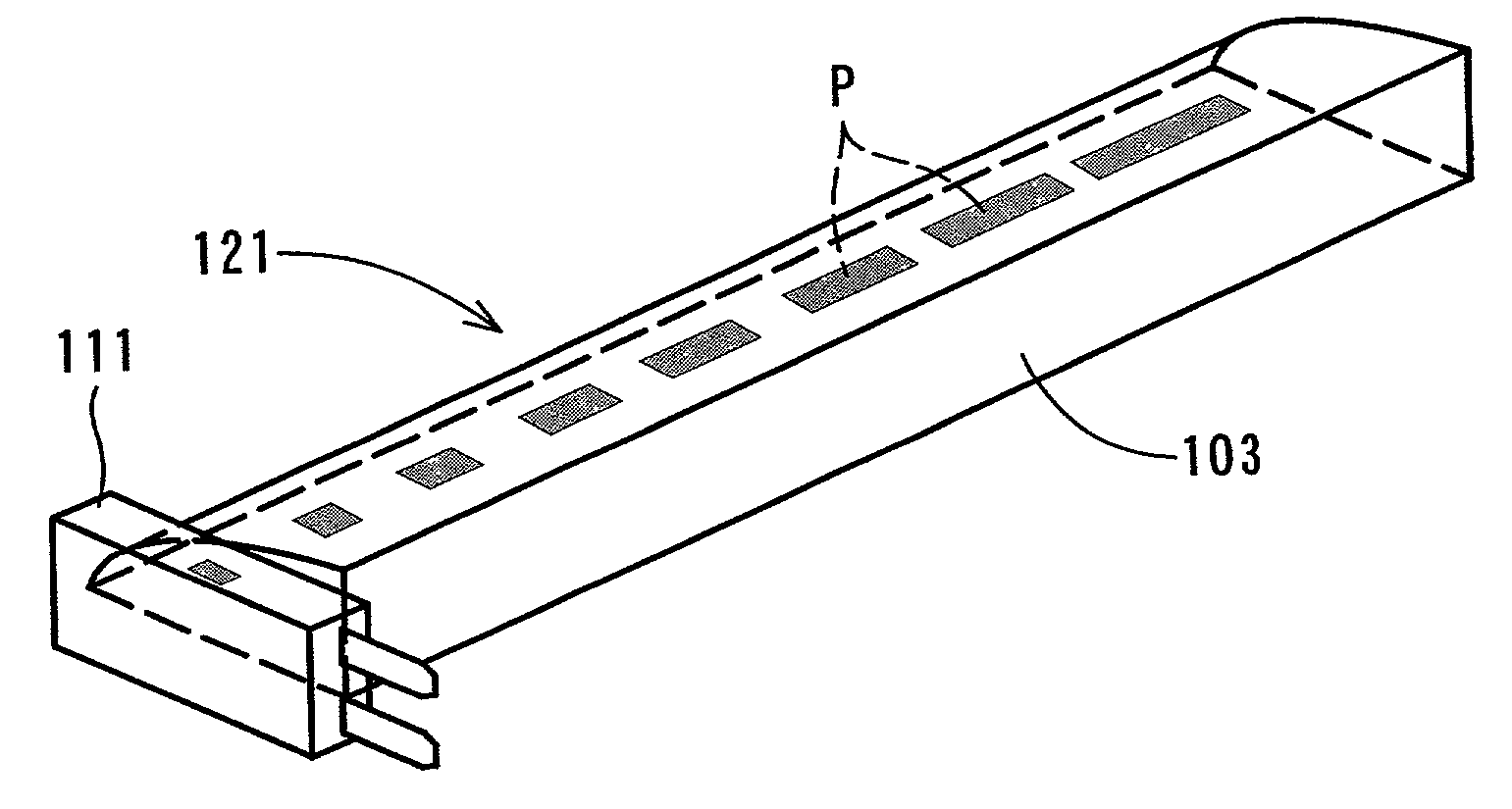
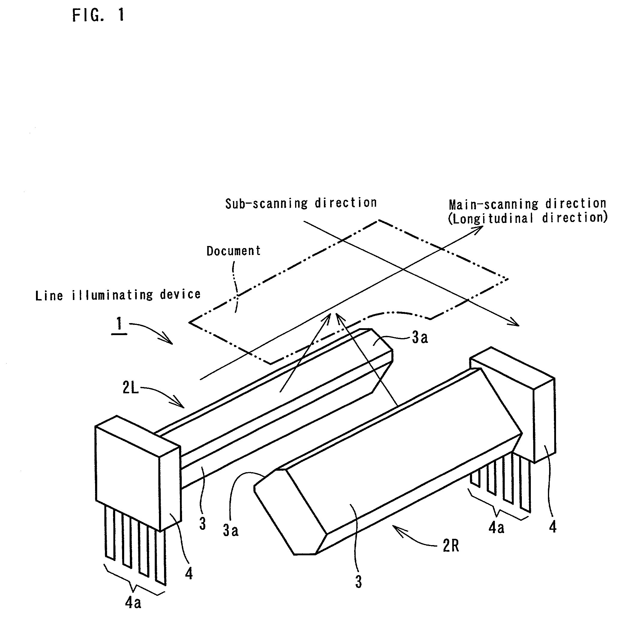
[0070]FIG. 1 is a perspective view showing a line illuminating device according to the present invention. As show in FIG. 1, the line illuminating device 1 has two illuminating units 2L and 2R alternately arranged. Each illuminating unit 2L and 2R has a light-emitting source base plate 4 attached to one end of a light guide 3.

[0071]The light guide 3 is made of a resin with high light-transmission properties such as acryl and polycarbonate or an optical glass with high light-transmission properties. The cross-sectional shape of the light guide 3 is polygonal and one side is adapted to serve as an emission plane 3a. Light-scattering patterns (not shown) are formed on the surface opposite to the emission plane 3a.

[0072]The light-emitting source base plate 4 is provided with one or a plurality of surface mounting type light-emitting diodes (LED) as a light-emitting source (not shown) and light from these light-emitting diodes is incident from an end surface of the light guide 3. Refere...

second embodiment

[0084]FIG. 5 is a cross-sectional view of a document-reading device incorporating a line illuminating device (the line illuminating device ) provided with two illuminating units with a casing. The document-reading device as shown in FIG. 5 comprises a frame 31 provided with two illuminating units 20L and 20R and a rod lens array 42, and a base plate 35 provided with a photoelectric conversion element (an image sensor) 34 mounted on the lower opening portion of the frame 31. Reference numeral 36 is a glass plate for a document stand and reference numeral 37 is a manuscript.

[0085]Each illuminating unit 20L and 20R comprises a light guide 21, a white casing 22 for covering the light guide 21, and a light-emitting source base plate provided with a light-emitting source (not shown). Reference numeral 21a is an emission plane and reference numeral 21b designates light-scattering patterns. The structure of each illuminating unit 20L and 20R is the same as that of the conventional illuminat...

third embodiment

[0092]In the line illuminating device two light guides 41 (illuminating units) are, as shown in FIG. 6(b), closely connected to each other and housed in a casing 42B. Also, as shown in FIG. 6(c), each light guide 41 (illuminating unit) may be integrally housed in its own housing portion formed in the casing 42C. The light guide 41 as shown in FIG. 6(c) is arranged so that the plane serving as the emission plane 41a does not coincide with the minor axis of the oval, but is positioned at a specific angle to the minor axis to shift the focus position.

[0093]FIG. 8 is a cross-sectional view of a line illuminating device according to a fourth embodiment and FIG. 9 is a cross-sectional view of a line illuminating device according to a fifth embodiment. FIG. 8(a) shows the cross-sectional structure of a single illuminating unit and FIGS. 8(b) and (c) show the cross-sectional structure of the line illuminating device according to the present invention. Similarly, FIG. 9(a) shows the cross-s...


PUM


Abstract

Two illuminating units 2L and 2R, each having a light guide provided at its one end, with a light-emitting source, are provided. Each illuminating unit is arranged in such a manner that light emitted from its emission plane irradiates the same area of a document-reading plane and the light-emitting source is situated on the opposite side in a main-scanning direction (i.e. the longitudinal direction). By alternately arranging two illuminating units, it is possible to offset characteristics of each illuminating unit so that uniformity and equalization of light intensity distribution can be improved. Since each-illuminating unit is arranged so that its emission plane is symmetric relative to a plane at right angles to the document-reading surface, it is possible to reduce shading that is produced on a document surface when the document surface is not flat.

Description

BACKGROUND OF THE INVENTION[0001]1. Field of the Invention[0002]The present invention relates to a line illuminating device for linearly illuminating a document in a document-reading device such as a contact-type image sensor.[0003]2. Description of the Prior Art[0004]Equipment such as a facsimile machine, a copying machine and an image scanner is provided with a document-reading device (an image reading device) such as an image sensor as a device for reading a document. One type of the document-reading device used is a contact-type image sensor of which the optical path length is short and which can be easily incorporated in the equipment. In this contact-type image sensor, it is necessary to read the portion to be read of the document by applying light in excess of the intensity of illumination readable by an illuminating device. In this case, the range to be illuminated is quite large in a main-scanning direction (i.e. in the longitudinal direction), but is a narrow, belt-like st...

Claims


Application Information

Patent Timeline
Patent Type & Authority Patents(United States)
IPC IPC(8): H04N1/04H04N1/031
CPCH04N1/031
Inventor IKEDA, MAKOTO
Owner NIPPON SHEET GLASS CO LTD
Why Eureka
Try Eureka