Heat dissipation device

a heat dissipation device and graphics card technology, applied in the direction of electrical apparatus casings/cabinets/drawers, instruments, etc., can solve the problems of heat sinks, adversely affecting the operation of graphics cards, and affecting the other electronic components of computer devices, so as to efficiently dissipate heat generated and heat dissipated from electronic components.

Inactive Publication Date: 2007-04-24
HON HAI PRECISION IND CO LTD +1
View PDF14 Cites 46 Cited by
  • Summary
  • Abstract
  • Description
  • Claims
  • Application Information

AI Technical Summary

Benefits of technology

[0007]A further object of the present invention is to provide a heat dissipation device which can efficiently dissipate heat from an electronic component.
[0008]To achieve the above-mentioned objects, a heat dissipation device in accordance with the present invention comprises a first heat sink mounted on one side of a VGA card on which a heat generating componnent is mounted to dissipate heat generated by the heat generating componnent, a second heat sink mounted on an opposite side of the card, a pair of heat pipes independent from and intercrossed with each other and connected between the first and second heat sinks for transferring heat from the first heat sink to the second heat sink, a pair of covers attached on the respective first and second heat sinks to form enclosed channels between the covers and the first and second heat sinks respectively, a pair of fans mounted between the covers and the first and second heat sinks for producing airflow through the channels to improve heat dissipation efficiency of the heat dissipation device.

Problems solved by technology

Such cards often have extremely large computing power and, as a consequence, generate substantial heat that if not dissipated will adversely affect operation of the graphics cards.
However, the two heat sinks 1, 2 are stacked on one side of the VGA cards and have a great height, which results in the heat sinks 1, 2 apt to interfere with other electronic components in a computer device.
Furthermore, the two heat sinks 1, 2 are stacked on one side of the VGA cards and unbalance weight is therefore exerted in opposite sides of the VGA cards, which results in the VGA cards easy to loose from connector ports of a circuit board in the computer device.

Method used


Image

  • Heat dissipation device
  • Heat dissipation device
  • Heat dissipation device

Examples


Embodiment Construction

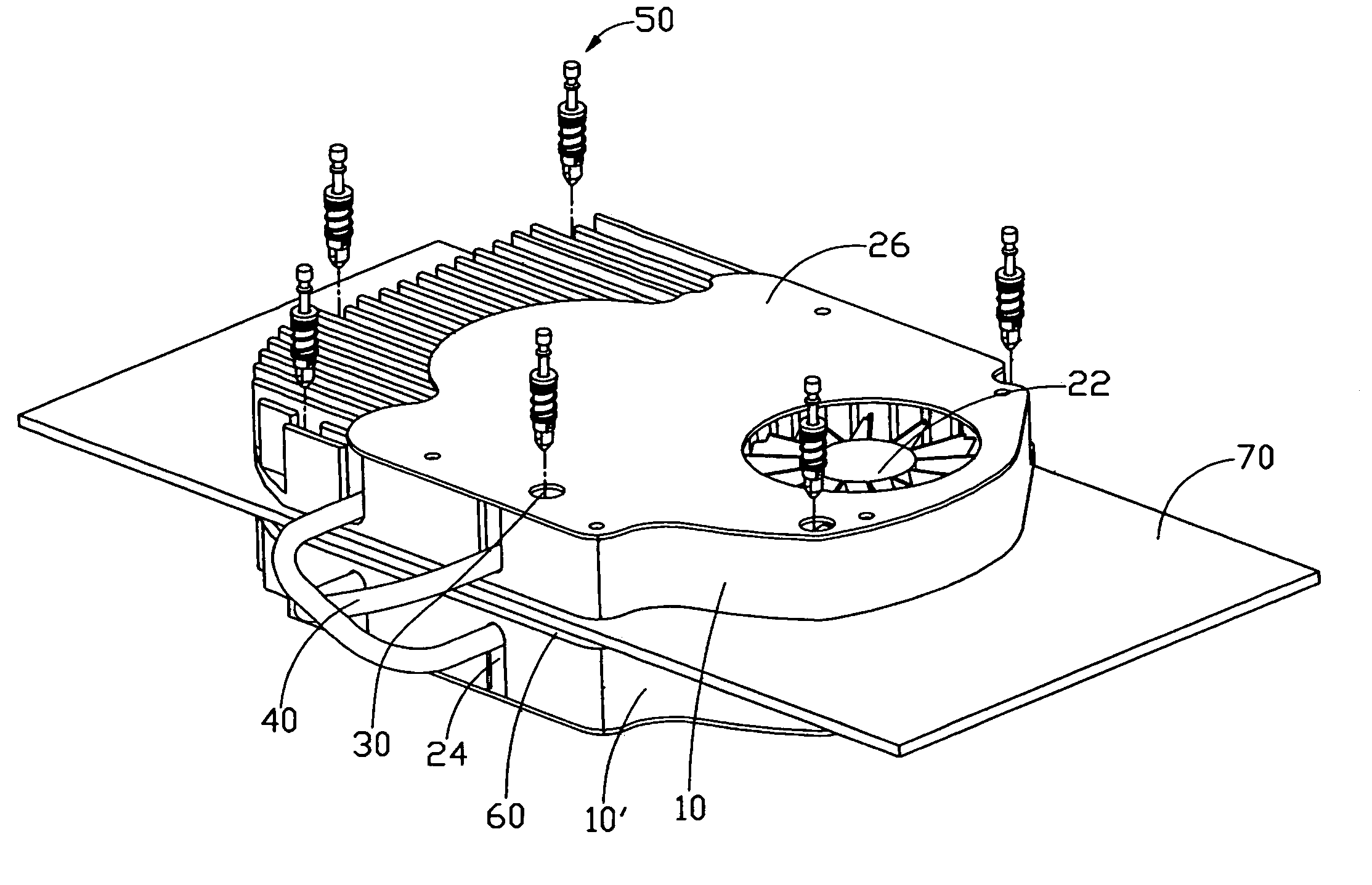
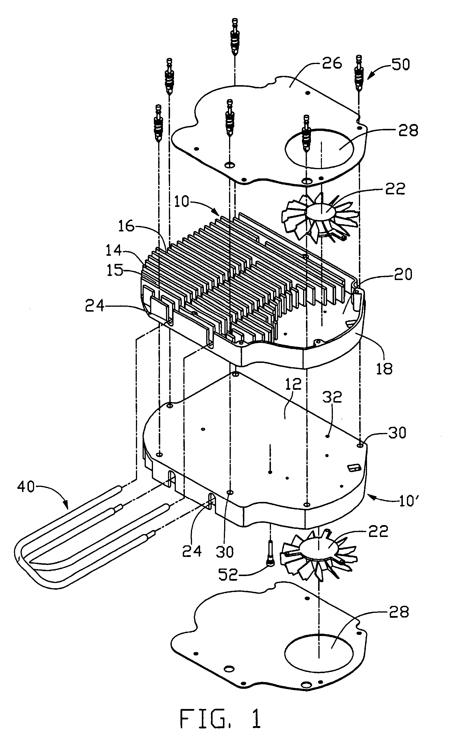
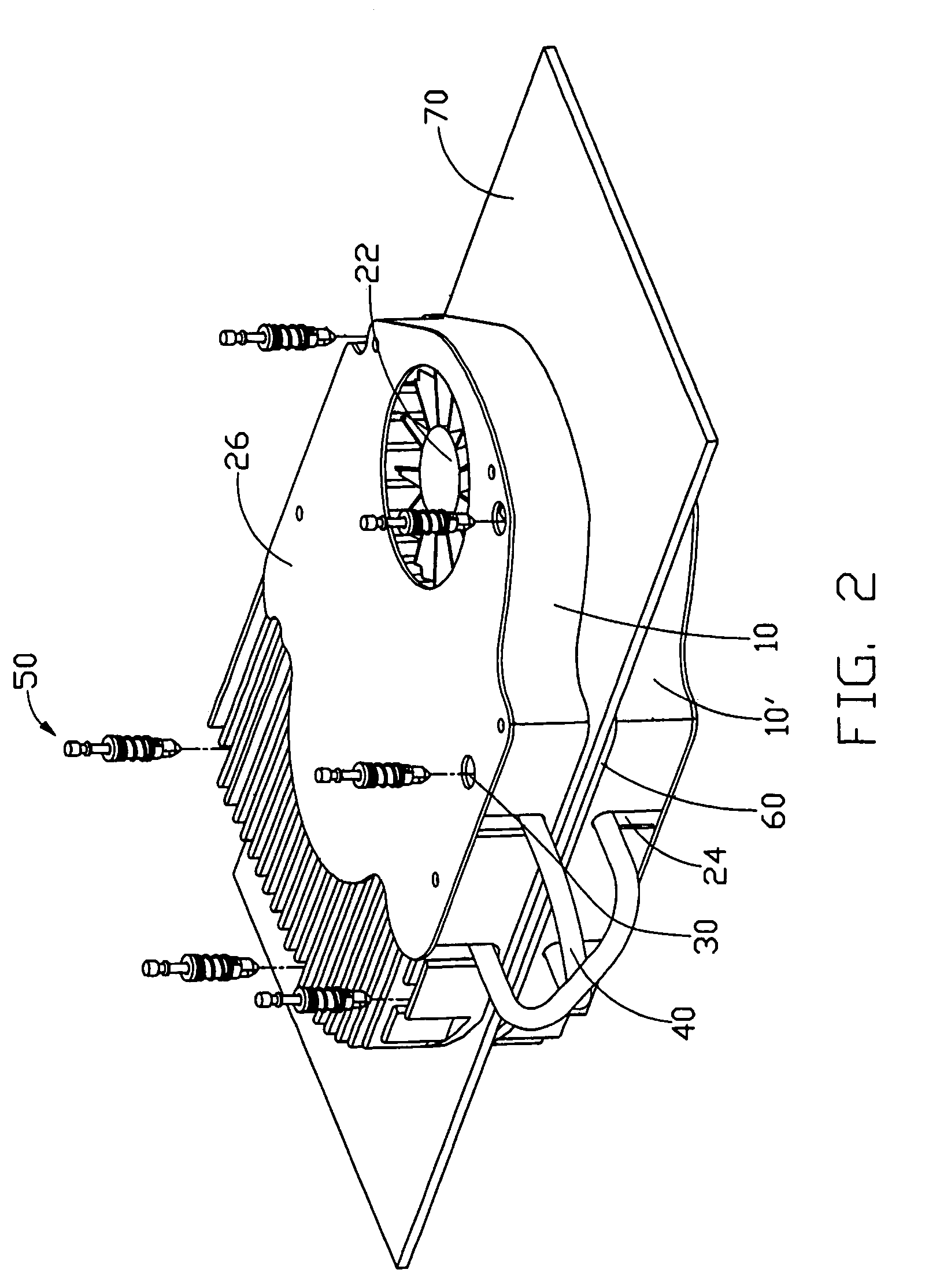
[0013]Referring to FIG. 1, a heat dissipation device in accordance with the preferred embodiment of the present invention comprises a first heat sinks 10, a second heat sink 10′, a pair of covers 26, and a pair of heat pipes 40.

[0014]The pair of hat sinks 10, 10′ have mirroring structures with each other. For simplifying illustration, the following illutsration takes the first haet sink 10 as an example. The first heat sink 10 comprises a base 12, and a plurality of spaced parallel fins 14 arranged on the base 12. A plurality of longituinal channels 15 is formed between adjacent fins 14. A wall 18 is formed on a peripheral edge of the base 12 and surrounds the fins 14 except an outlet 16 formed at ends of the fins 14. The outlet 16 aligns with the channels 15. A space 20 if formed between the wall 18 and opposit ends of the fins 14 opposing the outlet 16 for recieving a fan 22 therein. A plurality of through holes 30 is defined in thebase 12 adjacent to the periphery of the base 12 ...


PUM


Abstract

A heat dissipation device includes a first heat sink ( 10 ) mounted on one side of a video graphics adapter (VGA) card ( 70 ) on which a heat generating componnent is mounted to dissipate heat generated by the heat generating componnent, a second heat sink ( 10' ) mounted on an opposite side of the card, a pair of heat pipes ( 40 ) independent from and intercrossed with each other and connected between the first and second heat sinks for transferring heat from the first heat sink to the second heat sink, a pair of covers ( 26 ) attached on the respective first and second heat sinks to form enclosed channels ( 15 ) between the covers and the first and second heat sinks respectively, a pair of fans ( 22 ) mounted between the covers and the first and second heat sinks for producing airflow through the channels to improve heat dissipation efficiency of the heat dissipation device.

Description

BACKGROUND OF THE INVENTION[0001]1. Field of the Invention[0002]The present invention relates to a heat dissipation device for electronic devices, and particularly to a heat dissipation device for a graphics card apparatus.[0003]2. Prior Art[0004]In order to enable desktop and other computers to rapidly process graphics and game technology, add-on units generally referred to “graphics cards” or “VGA cards” are often installed in computer devices. Such cards include a separate processor, called a GPU, one or more memory chips and other required circuitry, all mounted to a circuit board. Such cards often have extremely large computing power and, as a consequence, generate substantial heat that if not dissipated will adversely affect operation of the graphics cards. Thus, a heat dissipation device is often attached to a top surface of a GPU to remove heat therefrom.[0005]FIG. 3 shows a conventional heat dissipation device for VGA cards. The heat dissipation device comprises a pair of h...

Claims


Application Information

Patent Timeline
Patent Type & Authority Patents(United States)
IPC IPC(8): G06F1/20H05K7/20
CPCH01L23/427H01L23/467H01L2924/0002
Inventor LEE, HSIEH, KUNXIA, WAN, LINLIU, HEBEN
Owner HON HAI PRECISION IND CO LTD
Why Eureka
Try Eureka