Three ply bolted temporary road mats and apparatus for manufacturing same

a technology of temporary road mats and bolts, which is applied in the field of temporary road surfaces, can solve the problems of limited torsional and bending strength, time-consuming and laborious, and prone to misalignment, and achieve the effect of reducing assembly stresses on the timbers and increasing bilateral stability

Inactive Publication Date: 2007-05-01
CAROLINA MAT
View PDF6 Cites 12 Cited by
  • Summary
  • Abstract
  • Description
  • Claims
  • Application Information

AI Technical Summary

Benefits of technology

[0008]The present invention provides an improved method for making bolted three ply temporary road mats wherein fastener holes are drilled concurrently by a gang drill apparatus into the freely assembled mat, the apparatus and mat indexed to successive positions for drilling while the preceding rows are fastened by carriage bolts, continuing until the mat is fully assembled. Resultantly, the completed mats can use fastener holes having close sliding fits with the bolts providing increased bilateral stability. Moreover, the fasteners are connected with only compressive forces substantially reducing assembly stresses on the timbers.

Problems solved by technology

The manual assembly, even with air powered nailing guns in time consuming and tiring and prone to misalignments.
This type of nailed construction provides limited torsional and bending strength, resulting loosening of the nailed joints and timber breakage.
Replacing a damage timber requires time consuming removal of all overlying timbers.
Such supplemental nailing can also splinter the timber resulting in a complete loss of nail holding strength.
The nailing of the timbers also precludes convenient repair and replacement of damaged timbers.
Bolted constructions have been suggested in the art, however, such mats are not known to be commercially available.
Notwithstanding the advantages of the bolted construction, production rates, even with fixtures and assembly tables, have been limited by the cycle times of the serially required operations.
Moreover, three ply mats have not been successfully produced.
The cumulative tolerances in the hole arrays for the three layers present's extreme alignment problems for assembly.
Approaches increasing the clearances between the holes and bolt shanks result in a loss of lateral structural stability.
Leveraging the boards to align the holes for assembly results in a stressed assembly condition that can result in timber fracture and surface warping.

Method used


Image

  • Three ply bolted temporary road mats and apparatus for manufacturing same
  • Three ply bolted temporary road mats and apparatus for manufacturing same
  • Three ply bolted temporary road mats and apparatus for manufacturing same

Examples


Embodiment Construction

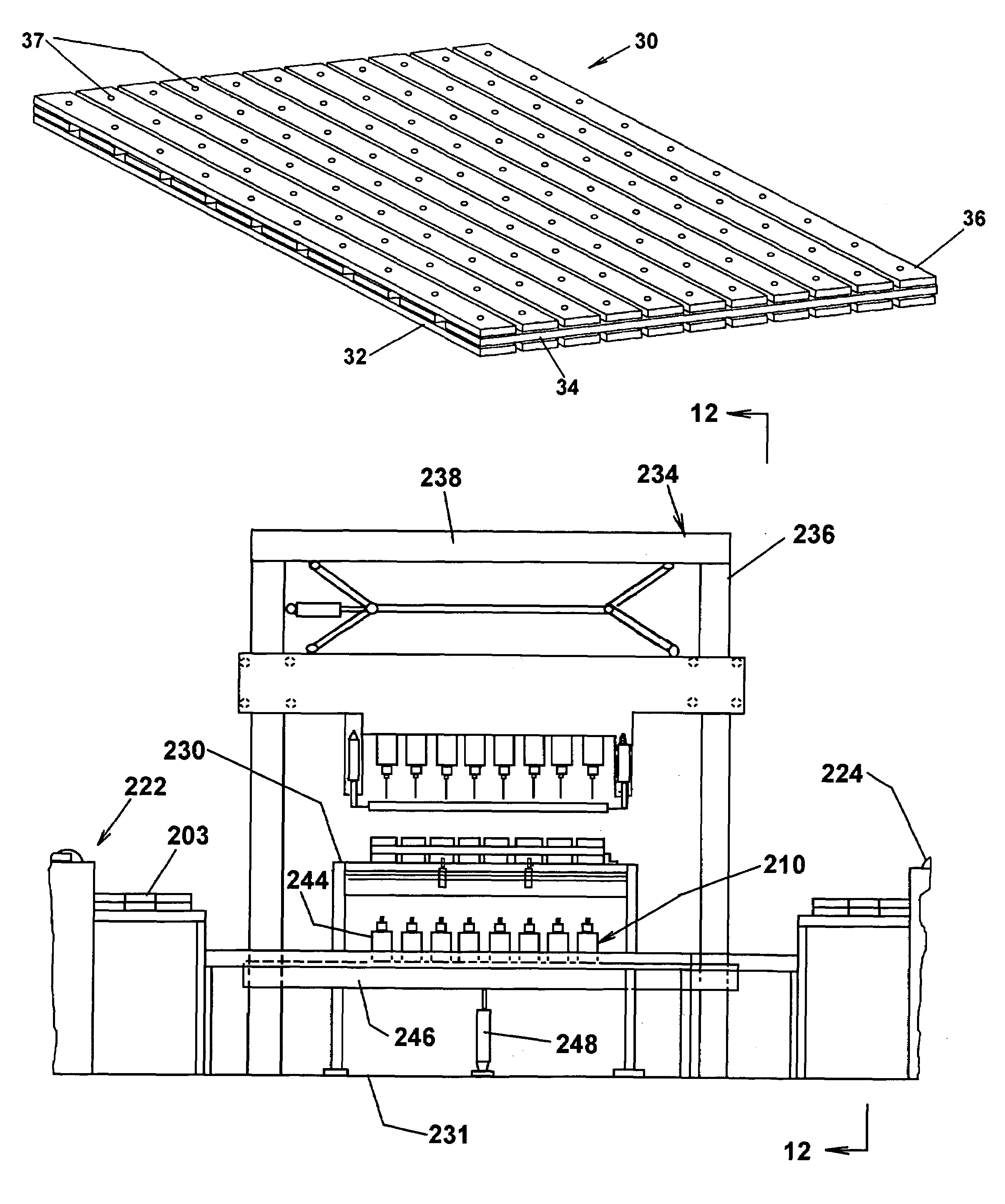
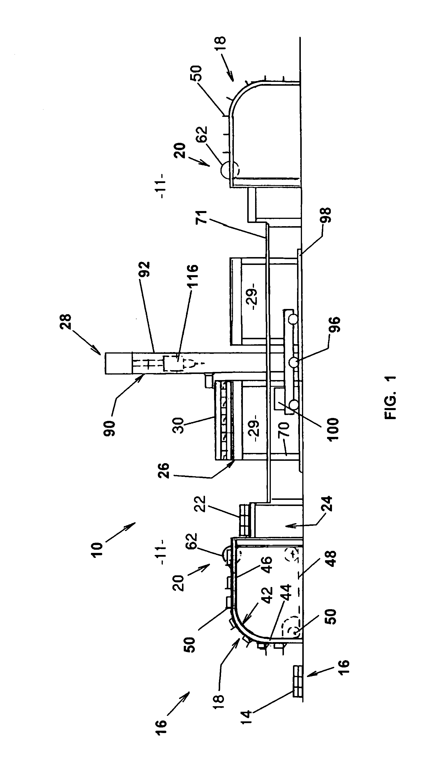
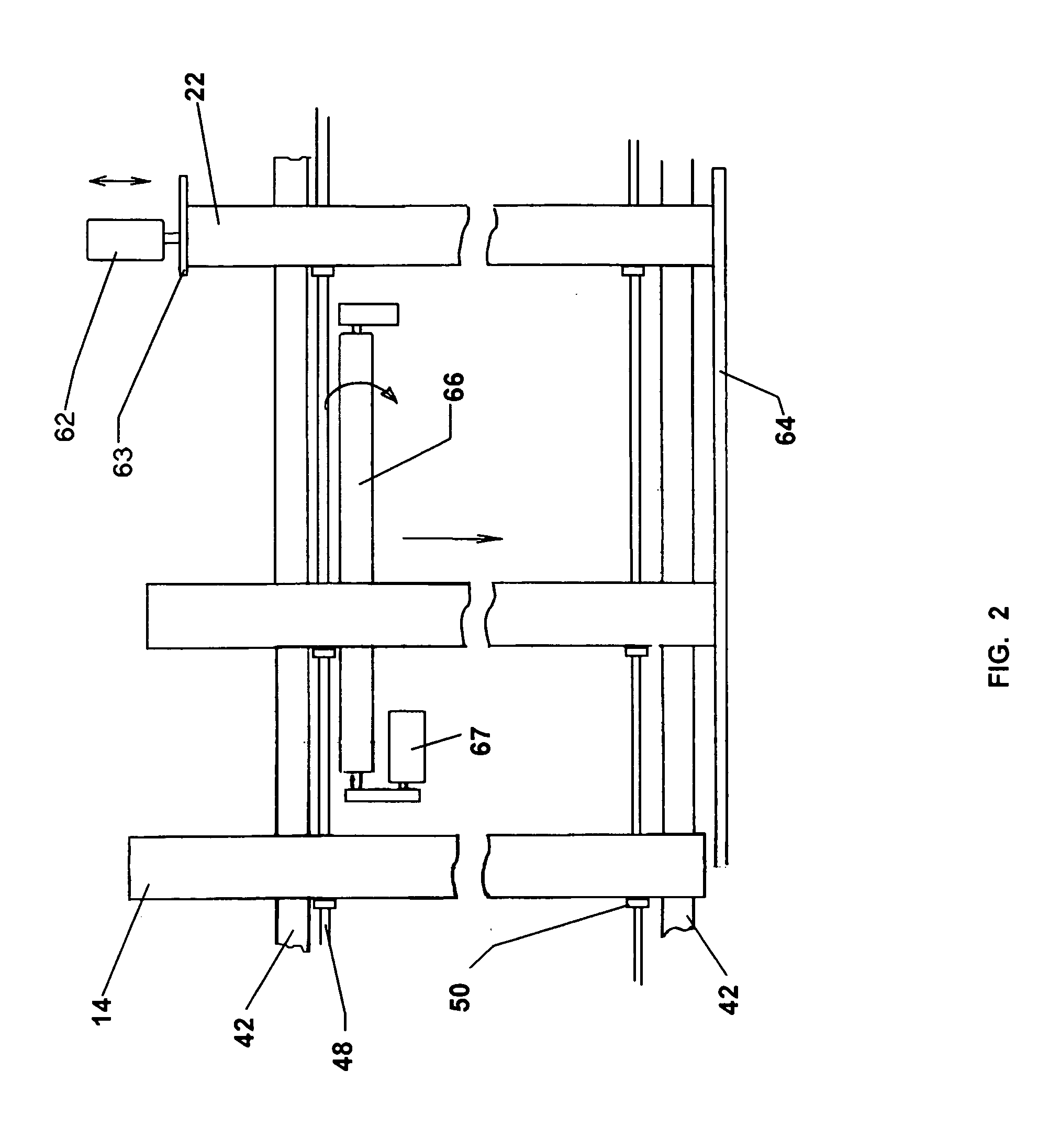
[0032]Referring to the drawings for the purpose of illustrating a preferred embodiment of the invention and not for limiting same, FIG. 1 shows an assembly apparatus 10 for the manufacture of temporary road mats. The apparatus 10 comprises a pair of in-line multilevel assembly lines 11. At the outer end of each line 11 rough wooden timbers 14 are delivered to a loading area 16, transferred by conveyor 18 through trimming station 20 to produce finished timbers 22 and unloaded at transfer area 24. The finished timbers 22 are assembled on assembly tables 26, drilled at vertical locations by a mobile gang drill 28, and fastened at underlying fastener bays 29. Fully assembled mats are removed from the assembly tables 26 by suitable material equipment such as overhead cranes or mobile fork lifts.

[0033]Referring to FIGS. 7 through 10, a completed temporary road mat 30, according to one embodiment, comprises three mutually perpendicular layers of spaced finished timbers. The width and lengt...


PUM

PropertyMeasurementUnit
lengthaaaaaaaaaa
lengthaaaaaaaaaa
lengthaaaaaaaaaa

Abstract

An apparatus for making temporary road mats characterized by multiple layers of mutually perpendicular elongated timbers having an array of vertical intersections aligned in lateral rows. The apparatus includes a gang drill that moves relative to a roughly assembled mat for sequentially drilling the lateral rows of intersections.

Description

RELATED APPLICATION[0001]This application is a continuation-in-part application of U.S. Ser. No. 10 / 407,992 filed on Apr. 7, 2003 in the name of Ronald Harrison and entitled “Apparatus for Assembling Temporary Road Mats”, which issued as U.S. Pat. No. 6,745,452.FIELD OF THE INVENTION[0002]The present invention relates to temporary road surfaces and, in particular, to apparatus for manufacturing and assembling three ply temporary road mats.BACKGROUND OF THE INVENTION[0003]Temporary road mats are used extensively to allow vehicles and equipment to reach locations not serviced by permanent roads, particularly under conditions where ground surface would not support the traffic or where the temporary nature of use does not warrant the time and expense of a permanent road. The mats are generally constructed in multiple layers of heavy wood timbers in crisscrossing layers. The mats may also be provided with interlocking joints for connecting with adjacent mats as disclosed in U.S. Pat. No....

Claims


Application Information

Patent Timeline
Patent Type & Authority Patents(United States)
IPC IPC(8): B23B39/18B23B39/16B23G1/20B27C3/04B27B5/04B27M3/00B32B21/13E01C9/08E01D15/12E01D21/00
CPCB23B39/161B27C3/00B27M3/0046E01C9/086B27B5/04Y10T408/3811Y10T29/5124Y10T29/49947Y10T408/385Y10T29/5107Y10T29/49948Y10T29/53978Y10T29/5136Y10T408/35Y10T408/3828
Inventor HARRISON, RONALD
Owner CAROLINA MAT
Why Eureka
Try Eureka