Saw blade with cutting depth gauge

a technology of depth gauge and saw blade, which is applied in the direction of gear teeth, gear chain, gear-teeth manufacturing apparatus, etc., can solve the problems of difficult adjustment accuracy of such devices, wear or other obscure effects, and the imprinting of depth gauges on saw blades

Active Publication Date: 2007-05-01
SAINT GOBAIN ABRASIVES INC
View PDF27 Cites 38 Cited by
  • Summary
  • Abstract
  • Description
  • Claims
  • Application Information

AI Technical Summary

Problems solved by technology

However, many such devices are difficult to adjust accurately.
Other devices, such as depth gauges imprinted onto saw blades, tend to be difficult to see, particularly in low-light conditions, and may be worn away or otherwise obscured during use.

Method used


Image

  • Saw blade with cutting depth gauge
  • Saw blade with cutting depth gauge
  • Saw blade with cutting depth gauge

Examples


example

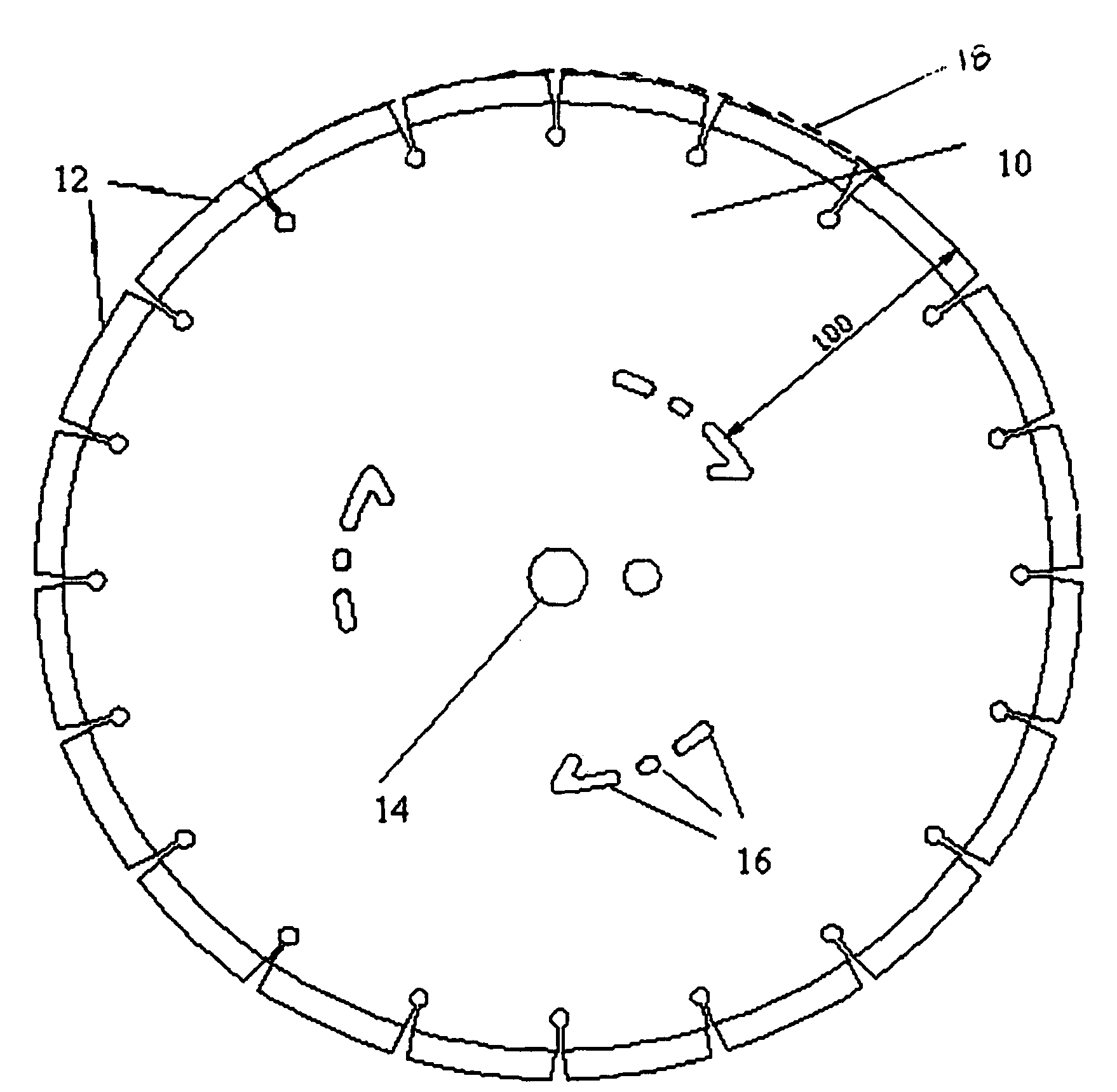
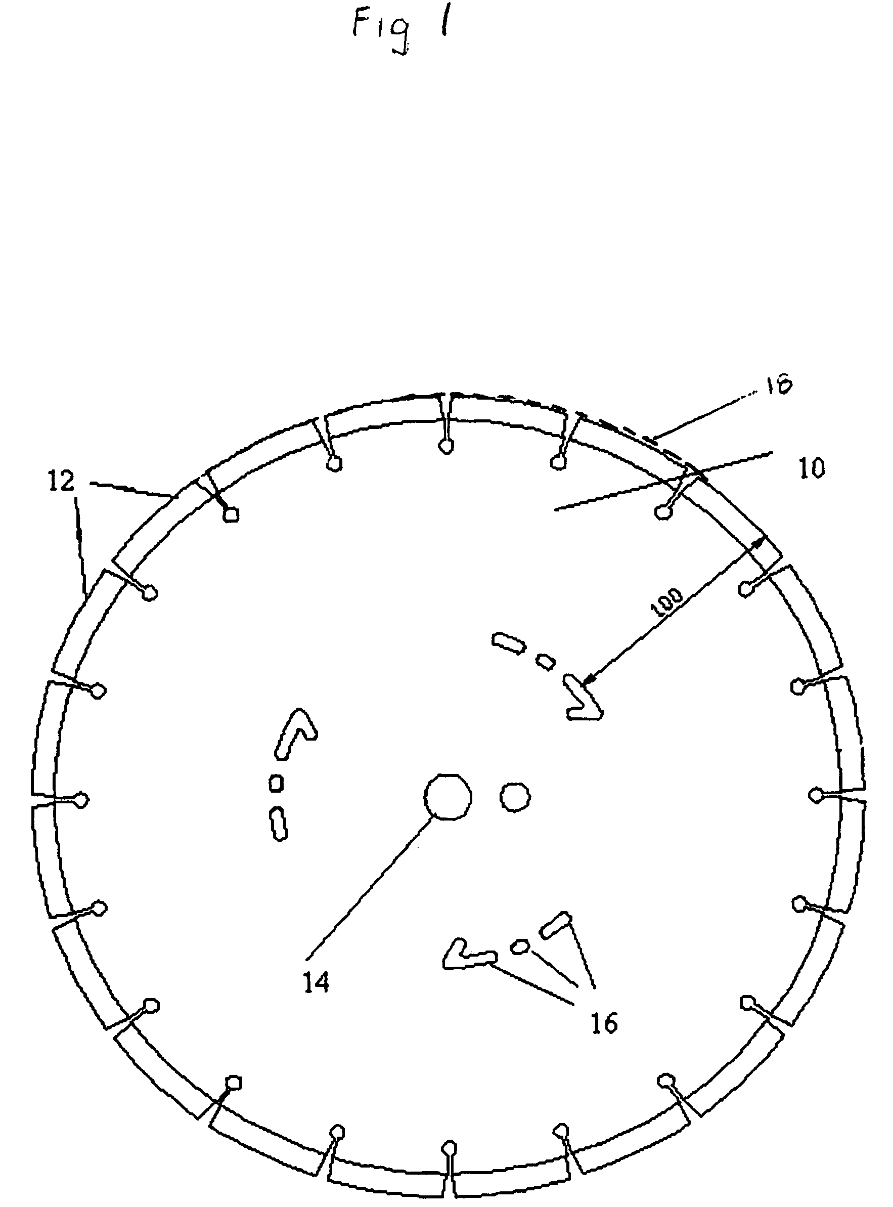
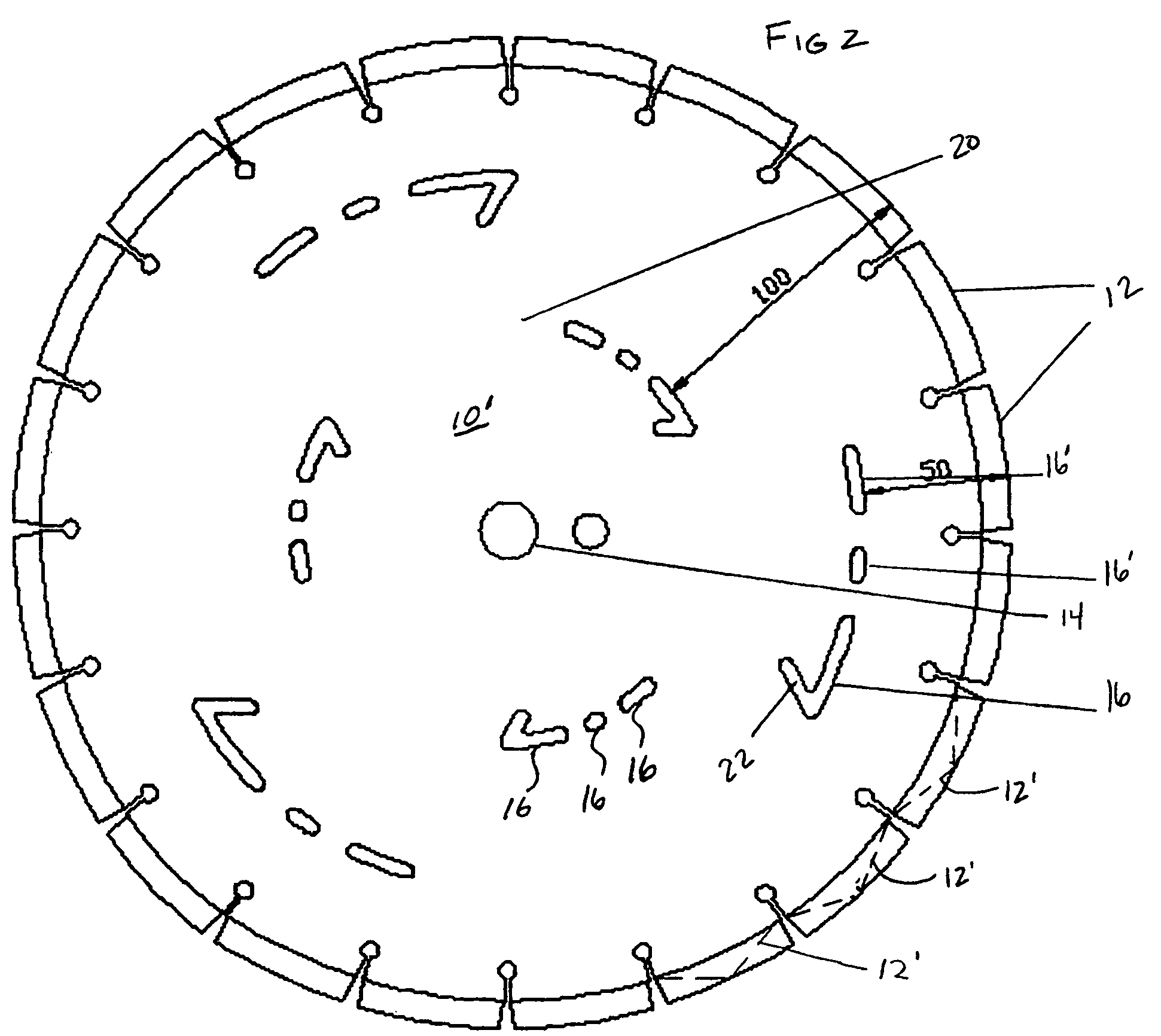
[0036]An otherwise conventional saw blade (NORTON™ SERVICE LINE, Super Asphalt Evo, 350 mm outside diameter, with diamond cutting teeth, manufactured by Saint-Gobain Abrasives S. A., Bascharage, Luxembourg) was modified to include perforations 16 substantially as shown and described hereinabove with respect to blade 10 of FIG. 1. Sets of perforations 16 were disposed along diameters spaced respectively 50 mm and 100 mm radially inward of the periphery of the saw blade 10.

[0037]This blade 10 was mounted to a walk behind floor saw (Clipper CSB1P13, manufactured by Saint-Gobain Abrasives S. A., Bascharge, Luxembourg) and used to cut into a floor. During cutting, a user was able to sight across the floor to the notional rings formed in blade 10 by perforations 16. Thus, while in operation, the perforations 16 provided a visual means by which the user was able to adjust the depth of cut. Cutting progressed until one of the notional rings was disposed at a predetermined elevation relative...


PUM

PropertyMeasurementUnit
diameteraaaaaaaaaa
diametersaaaaaaaaaa
diametersaaaaaaaaaa

Abstract

Cutting tools are provided that include a circular core with a cutting means located on its periphery, a central bore to receive an arbor of a rotating power tool and one or more perforations extending through the central core. The perforations are disposed along a circumference disposed concentrically with, and between, the central bore and the periphery. The perforations are arranged to form an annular window through the core which corresponds to a predetermined cutting depth during rotational operation of the tool.

Description

BACKGROUND[0001]1. Technical Field[0002]This invention relates to saw blades, and more particularly to a saw blade having an integral depth indicator.[0003]2. Background Information[0004]Cutting tools are often used to cut or drill to a desired depth which is only partway through a workpiece. In these situations it is necessary to control the depth of the cut. Some cutting tools, such as power saws and walk behind floor saws, are often equipped with a device that allows one to adjust the depth of cut. However, many such devices are difficult to adjust accurately. Other devices, such as depth gauges imprinted onto saw blades, tend to be difficult to see, particularly in low-light conditions, and may be worn away or otherwise obscured during use. Often the operator must stop the saw to measure the actual depth achieved. Additional adjustments must then be made if the target depth has not been achieved. Oftentimes, such measurement must be repeated several times to ensure that a desire...

Claims


Application Information

Patent Timeline
Patent Type & Authority Patents(United States)
IPC IPC(8): B28D1/04
CPCB23D61/025Y10T83/9319Y10T83/828Y10T83/9403
Inventor GAIDA, OLIVIER PHILIPPEPICHOFF, FRANCK JACQUES DOMINIQUE
Owner SAINT GOBAIN ABRASIVES INC
Why Eureka
Try Eureka