Illumination apparatus of light emitting diodes and method of heat dissipation thereof

a technology of light-emitting diodes and illumination apparatuses, which is applied in the direction of lighting and heating apparatus, semiconductor devices for light sources, and household stoves or ranges. it can solve the problems of noise and reliability problems, reduce the service life of led illumination apparatuses without fans, and difficult to design effective heat dissipation means, so as to increase the service life of light-emitting diodes and effective heat dissipation. , the effect of dissi

Inactive Publication Date: 2007-05-01
ADVANCED THERMAL DEVICES
View PDF9 Cites 125 Cited by
  • Summary
  • Abstract
  • Description
  • Claims
  • Application Information

AI Technical Summary

Benefits of technology

[0010]It is another one of objectives of the present invention to provide an illumination apparatus of light emitting diodes associated with a loop heat pipe device used to dissipate the heat generated from the light emitting diodes away effectively and further to increase the service life of the light emitting diodes.
[0011]It is another one of objectives of the present invention to provide an illumination apparatus of light emitting diodes with a heat dissipation device. The heat dissipation device not only has an effective heat dissipation ability but also its structure is simple and easy to be fabricated or implemented on the illumination apparatus to make the illumination apparatus of light emitting diodes have higher economic value.
[0012]According to the above-mentioned objectives, the present invention provides an illumination apparatus of light emitting diodes mainly including an illumination apparatus and a loop heat pipe device. The illumination apparatus including a base, a plurality of light emitting diodes and a cover. The plurality of light emitting diodes are attached on the base, and the cover has a shell body with a first opening at its one terminal and a second opening at the opposite terminal to provide a light ray exit. The shell body encloses the base as well as the plurality of light emitting diodes to guide the light generated from the light emitting diodes to the light exit. The loop heat pipe device includes a evaporator, a condenser, a vapor connecting pipe and a liquid return flow connecting pipe. The evaporator has a body with a vapor outlet, a return flow entrance and a chamber having volatile liquid therein. The evaporator is associated with the base tightly, and one terminal of the vapor connecting pipe communicates with the vapor outlet and the another terminal of the vapor connecting pipe communicates with one of entrances of the condenser, wherein the condenser is associated with the shell body of the cover. One terminal of the liquid return flow connecting pipe communicates with one of exits of the condenser and the another terminal of the return flow connecting pipe communicates with the return flow entrance. The base of the illumination apparatus conducts and transmits the heat generated form the light emitting diodes into the shell body of the cover via the loop heat pipe device and then the heat is dissipated away by the large area of exterior surface of the cover, and that makes the present illumination apparatus have an effective heat dissipation ability, and further increases the service life of the present illumination apparatus.

Problems solved by technology

The main bottleneck for the high-power illuminating technology is the insufficient heat dissipation ability of the traditional illumination apparatus of light emitting diodes often leads to the light emitting diodes in a high operational temperature to decrease theirs service life, further, even to cause them to burn down.
As a high-power or high-brightness illumination apparatus of light emitting diodes concerned, such as above 30˜100 W (watt), it is hard to design an effective heat dissipation means for the LED illumination apparatus without fans.
As the above-mentioned descriptions, the traditional method of heat dissipation usually requires a large space for setting up the plurality of cooling fins near the illumination apparatus and further needs to install an electric fan, that causes noise and reliability problems when it was used outdoors.
Another method of heat dissipation is adapting a conventional heat pipe device, however, the heat dissipation ability is limited due to the rigidity of the conventional heat pipe device and the limited length of conventional heat pipe device, usually can not be longer than 30 cm.
The heat dissipation ability of a conventional heat pipe device is thus mostly less than 30 W. Therefore, the other traditional method also can not solve the heat dissipation problem of the high-power illumination apparatus of light emitting diodes effectively.

Method used


Image

  • Illumination apparatus of light emitting diodes and method of heat dissipation thereof
  • Illumination apparatus of light emitting diodes and method of heat dissipation thereof
  • Illumination apparatus of light emitting diodes and method of heat dissipation thereof

Examples


Embodiment Construction

[0024]The invention will be explained in detail in accordance with the accompanying drawings. It is necessary to illustrate that the drawings in the below could be in simplified forms and not drawn in proportion to the real cases. Further, the dimensions of the drawings are enlarged for explaining and understanding more clearly.

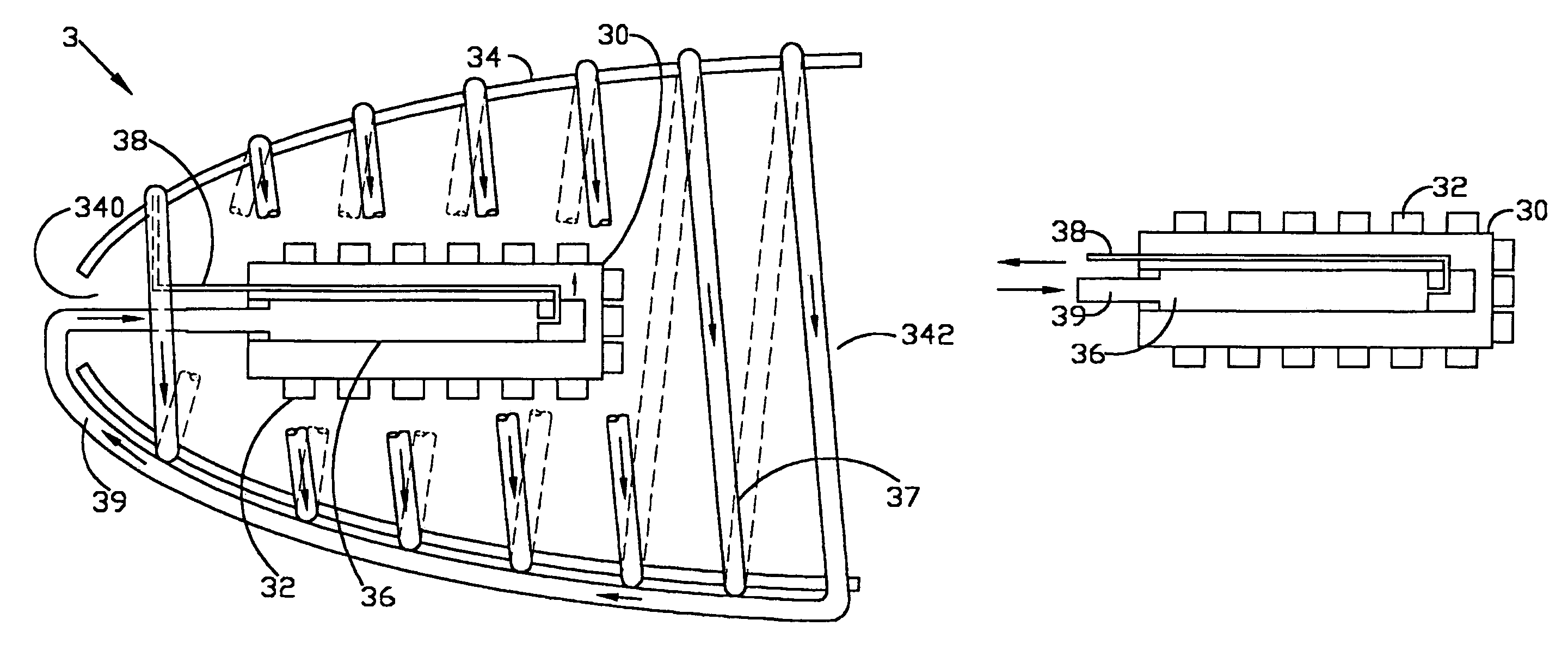
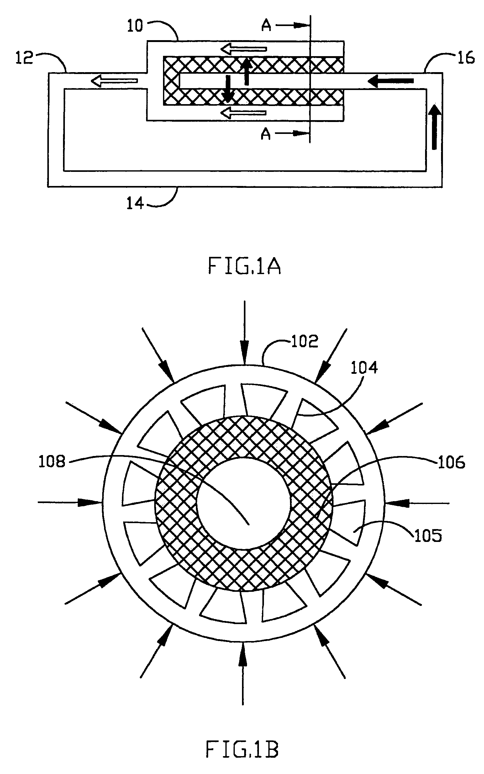
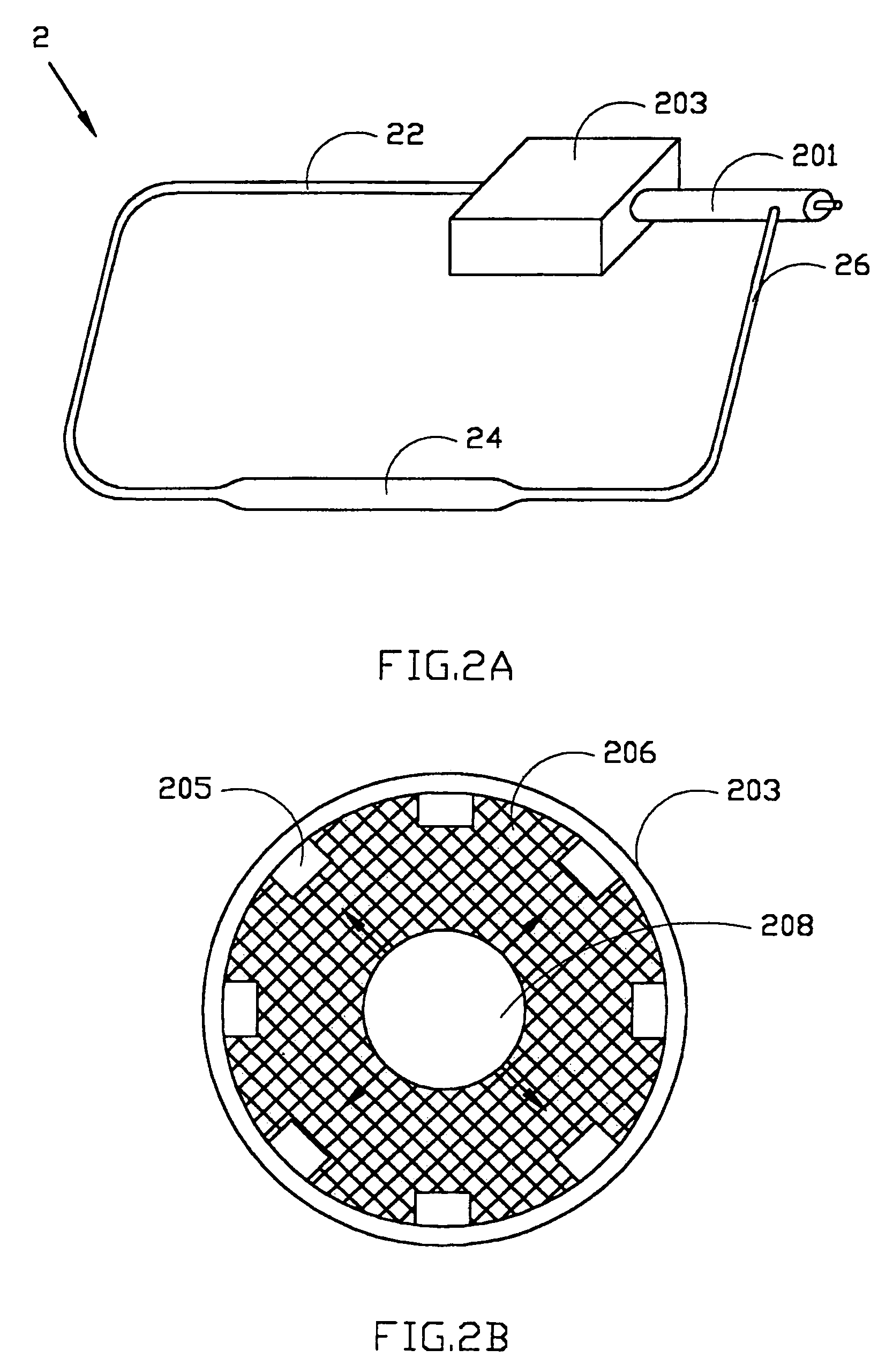
[0025]The loop heat pipe (LHP) device has many kinds of characters or advantages, for example, high heat transport rate (30 W˜6000 W), far distance heat-transferring property (03.m˜10 m), flexibility property (the diameter of the connecting pipe of the loop heat pipe device can be less than 2 mm), non-directional property (not influenced by the gravity) and unidirectional heat-transferring property. Therefore, it is very appropriate to use the loop heat pipe device to solve the heat dissipation problem for the illumination apparatus of light emitting diodes with high power or high brightness.

[0026]By the characters of the loop heat pipe device, in the present...


PUM


Abstract

An illumination apparatus of light emitting diodes and method of heat dissipation thereof are provided. The present illumination apparatus is associated with a loop heat pipe (LHP) device. The LHP device includes a condenser communicating with an evaporator. The illumination apparatus includes a base having a plurality of light emitting diodes disposed thereon and a cover with a light exit enclosing the base. The evaporator is associated with the base and the condenser is associated with the cover. The heat generated from the light emitting diodes is conducted to the cover, and thereby dissipated away.

Description

[0001]This Nonprovisional application claims priority under 35 U.S.C. §119(a) on Patent Application No(s). 092126707 filed in Taiwan, Republic of China on Sep. 26, 2003, the entire contents of which are hereby incorporated by reference.BACKGROUND OF THE INVENTION[0002]1. Field of the Invention[0003]The present invention relates to an illumination apparatus of light emitting diodes with a heat dissipation device, and more particularly to an illumination apparatus of light emitting diodes associated with a loop heat pipe device.[0004]2. Description of the Prior Art[0005]Light emitting diode (LED) has many advantages, such as small volume, higher illumination efficiency, energy saving and so on. Especially, the photo-electrical power conversion efficiency of the light emitting diode has been rapidly improved during the last twenty years, thus the light emitting diode is regarded as the main illumination source in the future. For energy conservation, the light emitting diode will certai...

Claims


Application Information

Patent Timeline
Patent Type & Authority Patents(United States)
IPC IPC(8): B60Q1/00F21V29/00F21V7/20F28D17/00F21V29/505F28D15/02F28D15/04
CPCF21V29/004F21V29/006F21V29/77F28D15/043F21Y2101/02F21Y2115/10F21V29/56F21V29/51
Inventor HUANG, BIN-JUINE
Owner ADVANCED THERMAL DEVICES
Why Eureka
Try Eureka