Lancet dispenser

a dispenser and lancet technology, applied in the field of lancet dispensers, can solve the problems of increasing pain for users, disadvantageous manual operating steps, and inconvenient use of lancets on lancing devices,

a dispenser and lancet technology, applied in the field of lancet dispensers, can solve the problems of increasing pain for users, disadvantageous manual operating steps, and inconvenient use of lancets on lancing devices,

US7211096B2Inactive Publication Date: 2007-05-01ROCHE DIABETES CARE INC +1

Image

  • Lancet dispenser
  • Lancet dispenser
  • Lancet dispenser

Examples


Embodiment Construction

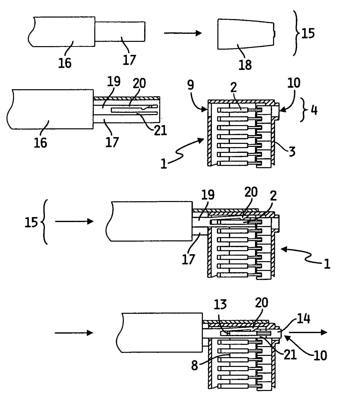
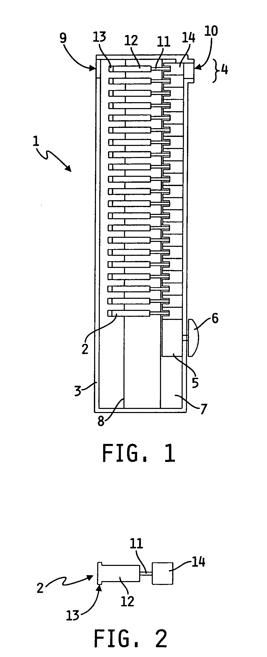
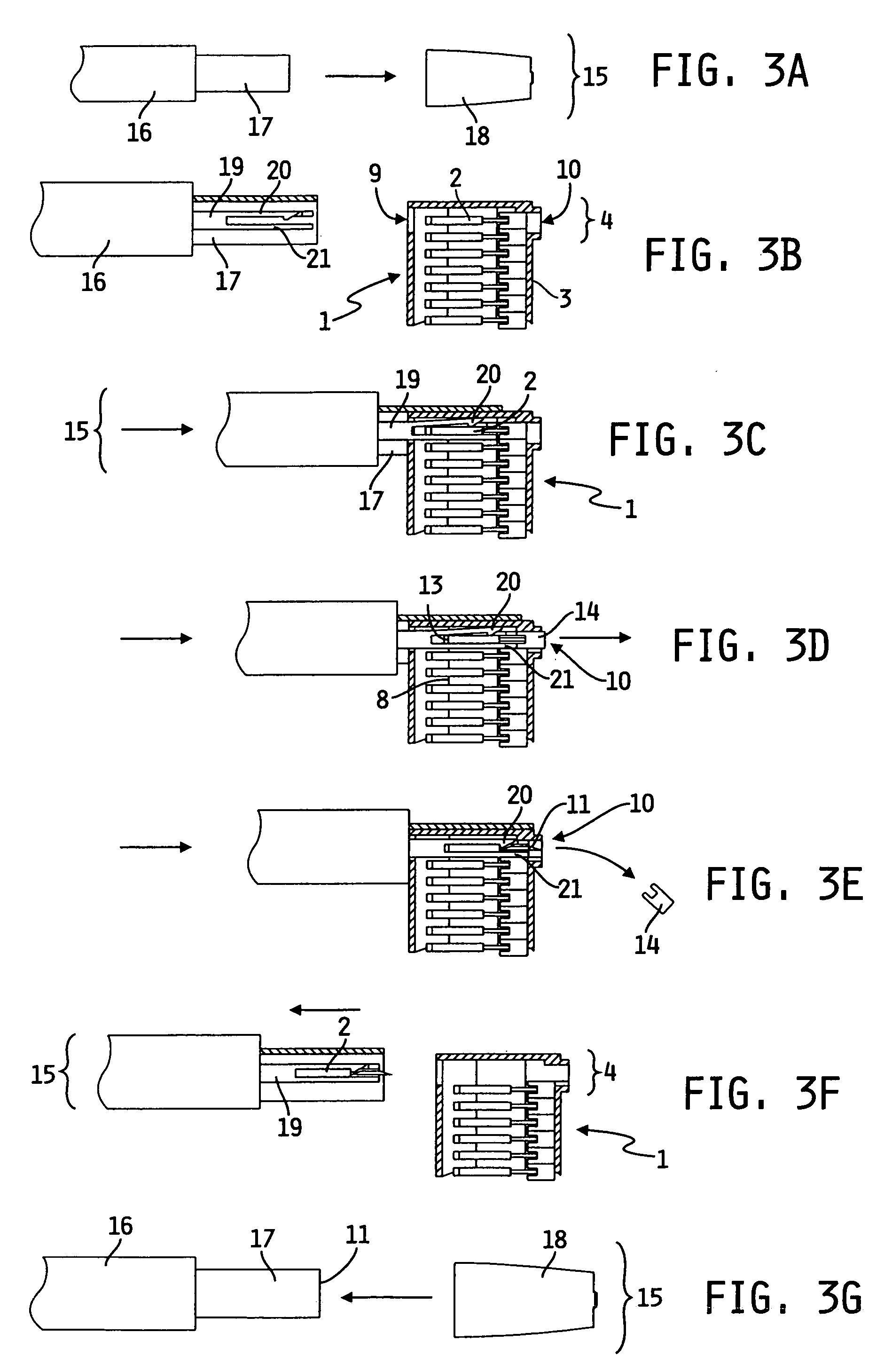
[0071]A diagram of a side-view of a particularly preferred embodiment of a lancet magazine (1) is shown in FIG. 1 in which a side wall of the housing (3) has been removed to enable a view into the lancet magazine (1) and of the lancets (2) contained therein. The lancet magazine (1) has essentially an elongate, flat cuboid shape in which the lancets (2) are arranged linearly next to one another each in pair-wise contact. The lancets can be manually pushed to the removal site (4) with the aid of a transport device (5) for which an operating knob (6) for the transport device (5) is provided on the outside of a long, narrow side of the lancet magazine (1). The transport device (5) can be moved continuously or discontinuously, for example with stops, with the aid of the operating knob (6). The position of the operating knob (6) allows the actual filling level of the magazine (1) to be displayed. As best shown in FIGS. 1, 3, and 4, lancets (2) are removed from the lancet magazine (1) in a...


PUM


Abstract

A system suitable for collecting a body fluid, in particular blood from a body region of a person to be examined which comprises a lancing device which is suitable for holding a lancet, a lancet magazine for storing two or several lancets which has a transport device for the lancets and has an opening into which the lancing device can be inserted to remove a lancet from the lancet magazine, and two or several lancets, and which comprises a method for removing a lancet from a lancet magazine in which a lancet located in the lancet magazine is manually or automatically transported into a removal position in the interior of the lancet magazine, a lancing device is partially inserted into the opening provided in the lancet magazine in the process of which the lancing device automatically grips the lancet located in the removal position when it is partially inserted and the lancing device with the gripped lancet is removed from the lancet magazine.

Description

CROSS-REFERENCE[0001]This application is a continuation of U.S. patent application Ser. No. 09 / 389,428, filed Sep. 3, 1999 now U.S. Pat. No. 6,783,537 and claims priority from German Application No. 198 40 8560, filed Sep. 7, 1998, the disclosures of which are incorporated by reference herein.BACKGROUND AND SUMMARY[0002]The invention concerns a system which is suitable for obtaining a body fluid, in particular blood, from a body region of a person to be examined, wherein the system contains a lancing device, two or several lancets and a lancet magazine for storing two or several lancets. The invention additionally concerns a lancing device, lancets and a lancet magazine which are suitable for use in a system according to the invention and it concerns a special method for removing a lancet from a lancet magazine.[0003]The examination of blood samples in clinical diagnostics enables an early and reliable detection of pathological states and the specific and well-founded monitoring of ...

Claims


Application Information

Patent Timeline
01 May 2007
Publication
US7211096B2
IPC
A61B17/32; A61B17/14; A61B5/15
CPC
A61B5/1411; A61B5/150022; A61B5/150412; A61B5/15186; A61B5/150564; A61B5/15153; A61B5/15161; A61B5/15174
Inventors
KUHR, HANS-JUERGEN; KINTZIG, HANS