Drive system including electric power devices

a technology of electric power devices and drive cases, which is applied in the direction of electric devices, dc-ac conversion without reversal, propulsion by batteries/cells, etc., can solve the problems of cooling which flows through the flow path and leaks into the drive cases along the connection interfaces between the case segments, and reduce the insulation performance of electric power devices. , to achieve the effect of preventing contact, reducing the number of components, and improving yield

Inactive Publication Date: 2007-05-01
AISIN AW CO LTD
View PDF7 Cites 40 Cited by
  • Summary
  • Abstract
  • Description
  • Claims
  • Application Information

AI Technical Summary

Benefits of technology

[0015]In is also effective to attach the inverter case to the drive case such that the inverter case extends over the case segments and to provide a plurality of sealing members, one interposed between each of the case segments and the inverter case. In such a case, no sealing surface extends across the interfaces between the case segments, so that the gap between the inverter case and the drive case can be more reliably sealed without being affected by the step, or misalignment, between the case segments which is formed due to processing errors and/or assembly errors.
[0016]Instead of the structure where the inverters are contained in a common inverter case which is attached to the drive case, the structure of the drive system may also be such that the inverters are fixed on a common base which is attached to one of the case segments and the flow path of the coolant is positioned between the case segment to which the inverters are collectively attached and the base. In such a case, the inverters can be blocked off from the flow path of the coolant by the base without providing a sealing member, and therefore the coolant can be reliably prevented from coming into contact with the inverters. In addition, the inverters can be more efficiently assembled onto the drive case compared to the case in which the inverters are individually attached to the ...

Problems solved by technology

In this case, however, the coolant's flow path interposed between the drive case and the inverters, for achieving heat insulation and cooling of the inverters, extends across the interfaces between the case segments, and there is a risk that the...

Method used


Image

  • Drive system including electric power devices
  • Drive system including electric power devices
  • Drive system including electric power devices

Examples


first embodiment

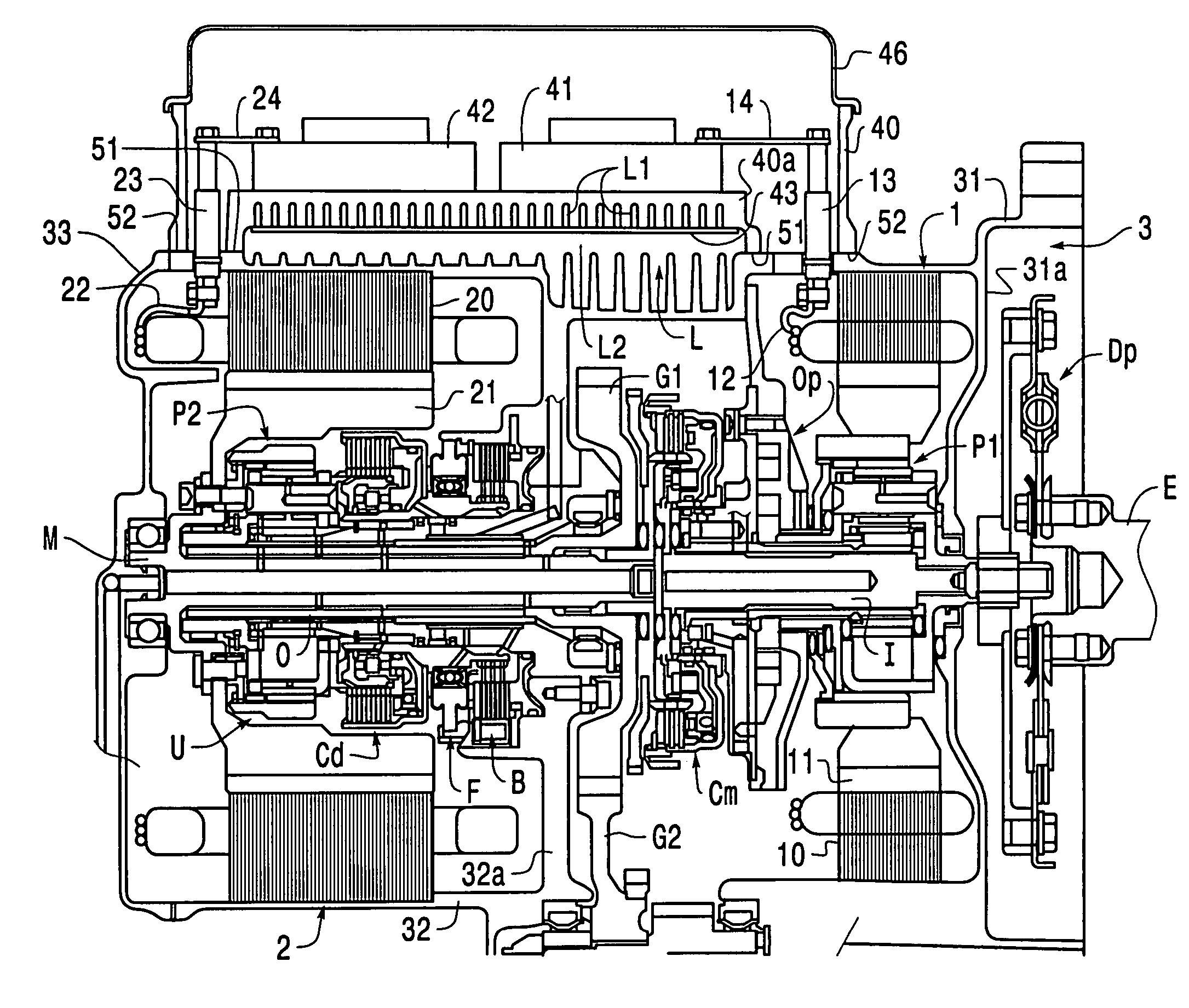
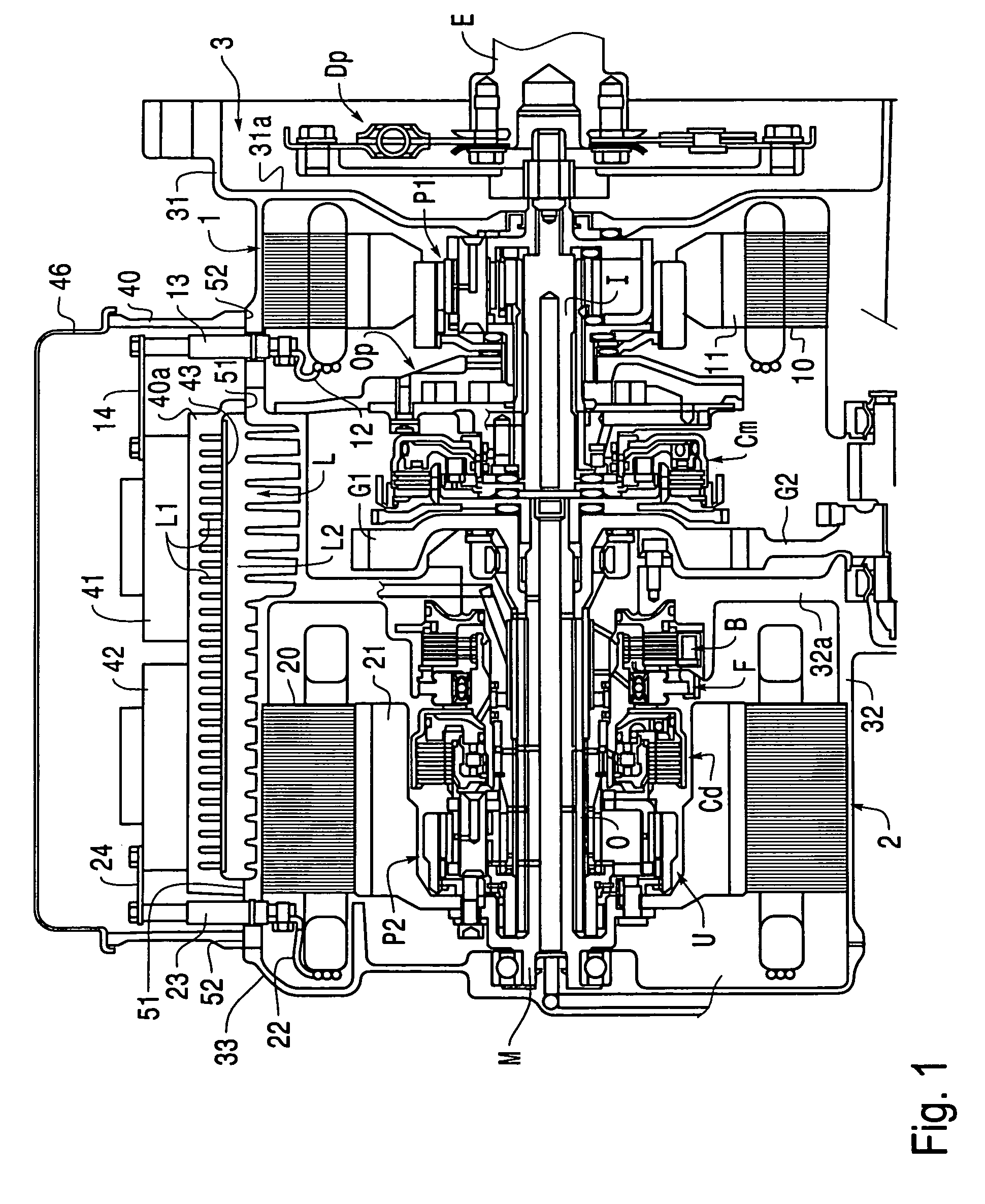
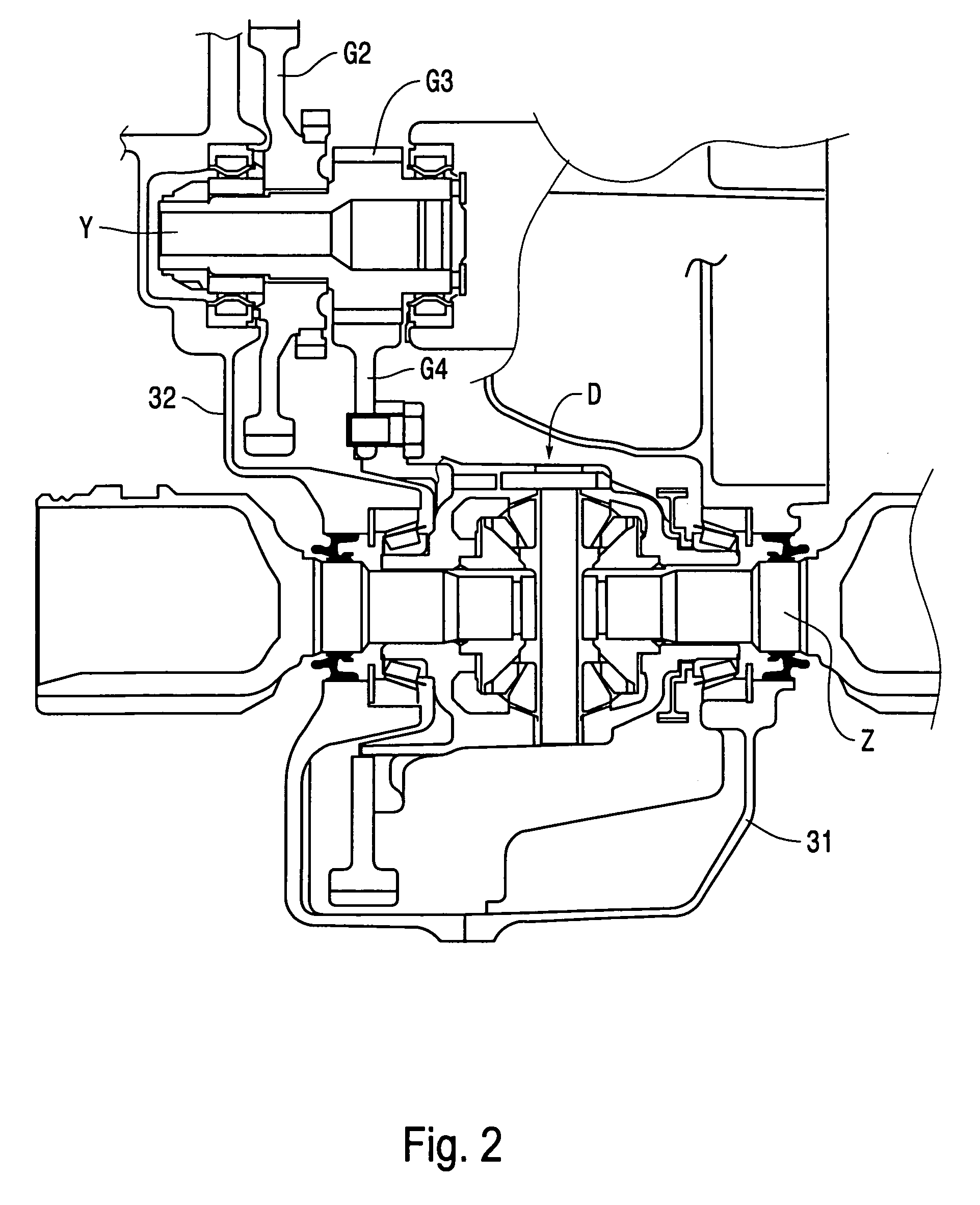
[0027]FIG. 1 shows a part of a developed sectional view of a drive system including electric power devices according to the invention, taken along an axial direction, and FIG. 2 shows the remaining part of the developed sectional view of the drive system. The drive system is a transaxle-type hybrid drive system which is intended to be used in a vehicle with a transversely mounted engine, and includes two electric power devices, a generator 1 used mainly for power generation and a motor 2 used for driving and energy regeneration, a mode-switching clutch Cm for switching a drive mode, an underdrive unit U for increasing the motor torque, and a differential unit D as main components.

[0028]In this drive system, a drive plate Dp having a damper, the generator 1, an oil pump Op, the mode-switching clutch Cm, a counter drive gear G1, and the motor 2 are mounted on a main shaft which is coaxially connected to an engine output shaft E in that order from the end adjacent to the engine. A plan...

third embodiment

[0045]The structure of the third embodiment is also suitable for a case in which the inverters 41, 42 are arranged on a common substrate and are included in a single module. In this case, if, for example, the substrate itself is structured as a heat sink, the structure for integrating the inverters 41, 42 with the drive system, similar to that shown in FIG. 6, and the cooling structure can be obtained at the same time.

[0046]In the present embodiment, a cover 46 which covers the inverters 41, 42 and their connection parts extends over the front case segment 31 and the rear case segment 32 of the drive case 3. Because a sealing member 52 provided between the cover 46 and the drive case 3 lies on a step, or misalignment, it is composed of a material which tolerates the step, similar to the sealing member provided between the inverter case and the drive case in the above-described embodiments. Other structures of the present embodiment are similar to those of the first embodiment. There...


PUM


Abstract

A drive system includes a plurality of electric power devices, a drive case having a plurality of case segments which are connected to each other, each of the electric power devices being contained in one of the case segments, and a plurality of inverters, one for each of the electric power devices. The inverters are collectively attached to one of the case segments, and a flow path of a coolant for cooling the inverters is positioned between the case segment to which the inverters are attached and the inverters. Accordingly, a cooling unit which performs heat insulation and cooling between the drive system and the inverters is positioned only on the outer surface of one of the case segments and does not extend across the connection interfaces between the case segments. Therefore, the risk of leakage of the coolant into the drive case can be substantially eliminated.

Description

[0001]This application claims priority from JP 2003-135106, filed May 13, 2003, the disclosure of which is incorporated herein by reference thereto.BACKGROUND OF THE INVENTION[0002]1. Field of Invention[0003]The invention relates to a drive system including a plurality of electric power devices, and more specifically relates to a technique for integrating inverters with a drive system for an electric vehicle or a hybrid vehicle.[0004]2. Description of Related Art[0005]As an example of a known drive system for a hybrid vehicle, Japanese Unexamined Patent Application Publication No. 6-328950 discloses a drive system including two electric power devices (in the present specification, the term “electric power device” generically refers to motors, motor generators, and generators) and a drive case constructed of case segments, each electric power device being contained in one of the case segments. The case segments are combined together such that the two electric power devices are mounte...

Claims


Application Information

Patent Timeline
IPC IPC(8): H02K9/00B60K1/00B60K6/26B60K6/40B60K6/405H02K5/08H02K5/20H02K5/22H02K9/02H02K11/00H02M7/48H05K7/20
CPCB60K6/365B60K6/405B60K6/445H02K11/0073B60K1/02B60K2001/003Y02T10/6239H02K11/33B60L3/003B60L7/14B60L15/20B60L15/2009B60L2210/40B60L2240/12B60L2240/36B60L2240/421B60L2240/423B60L2240/441B60L2240/443B60L2240/525B60L50/61B60L50/16Y02T10/62Y02T10/64Y02T10/72Y02T10/7072Y02T10/70
Inventor TAKENAKA, MASAYUKIYAMAGUCHI, KOZOKIDO, TAKAHIRO
Owner AISIN AW CO LTD
Why Eureka
Try Eureka