Monopulse radar system

a radar system and monopulse technology, applied in the field of monopulse radar system, can solve the problems of increasing the cost of parts used in such ultra-high frequency, phase error or amplitude error, and the inability to accurately calibrate the

Inactive Publication Date: 2007-05-01
HITACHI LTD
View PDF22 Cites 13 Cited by
  • Summary
  • Abstract
  • Description
  • Claims
  • Application Information

AI Technical Summary

Benefits of technology

[0019]The signal for calibration is used where the signal is always supplied to the output parts of the plurality of receiving antennas, and where a switch is provided on a calibration signal transmission line for supplying the signal calibration and a switch driving unit for controlling conducting and cut-off states of the switch is provided. As the control on the conducting and cut-off states, there are one for normally bringing the calibration signal transmission line to the cut-off state and bringing it to the conducting state upon calibration, and one for generating the conducting state of the switch periodically or with predetermined timing. In particular, a signal processing device such as a DSP is used to perform either one of the above-described calibrations automatically or with arbitrary timing, thereby correcting variations in characteristic developed after product shipment due to environmental variations, time variations in parts characteristic, etc. In the present embodiment, the accuracy of the angle detected by the monopulse radar can be maintained by ever-execution of the calibration.
[0021]As another preferred embodiment, the signal for calibration is modulated with a low frequency signal. Thus, the calibration signal is superimposed on a reflected signal, thus causing inconvenience. Namely, if the operation of an antenna is not perfectly stopped upon calibration, then a signal radiated from a transmitting antenna is reflected by an object present ahead of the antenna, which is then received by its corresponding receiving antenna depending on environments under which calibration is made. The present embodiment prevents such inconvenience that when a transmit signal is used as a signal for calibration as it is, this signal is superimposed on the calibration signal, so that accurate calibration cannot be performed. The present embodiment is also effective in preventing a low frequency signal converted by a mixer from being brought into a DC current in a homodyne type radar wherein the same ones are used for a local signal generator for generating a transmit signal and a signal generator for generating a local signal supplied to the mixer.

Problems solved by technology

In general, parts used in such an ultra-high frequency are expensive and large in part-to-parts characteristic variations as compared with parts used in a low frequency.
In the radar system using signals lying in a millimeter wave band, however, a phase error or an amplitude error is developed between channels due to the aforementioned reason, and an error is developed in a detected azimuth angle of target.
However, this will result in an increase in part cost.
Further, variations developed upon part assembly cannot be eliminated.
In such a method, however, the system becomes large-scale and takes a lot of trouble over its calibration work.
Therefore, the manufacturing cost thereof will increase due to the new addition of this work.
A problem arises in that any countermeasures referred to above do not take into consideration variations in characteristic after the shipment of each product, and the accuracy of a detected angle is deteriorated where variations in characteristic occur due to some kind of factors such as environmental variations, time variations in parts characteristic.

Method used


Image

  • Monopulse radar system
  • Monopulse radar system
  • Monopulse radar system

Examples


Embodiment Construction

[0038]Preferred embodiments of the present invention will hereinafter be described with reference to the accompanying drawings.

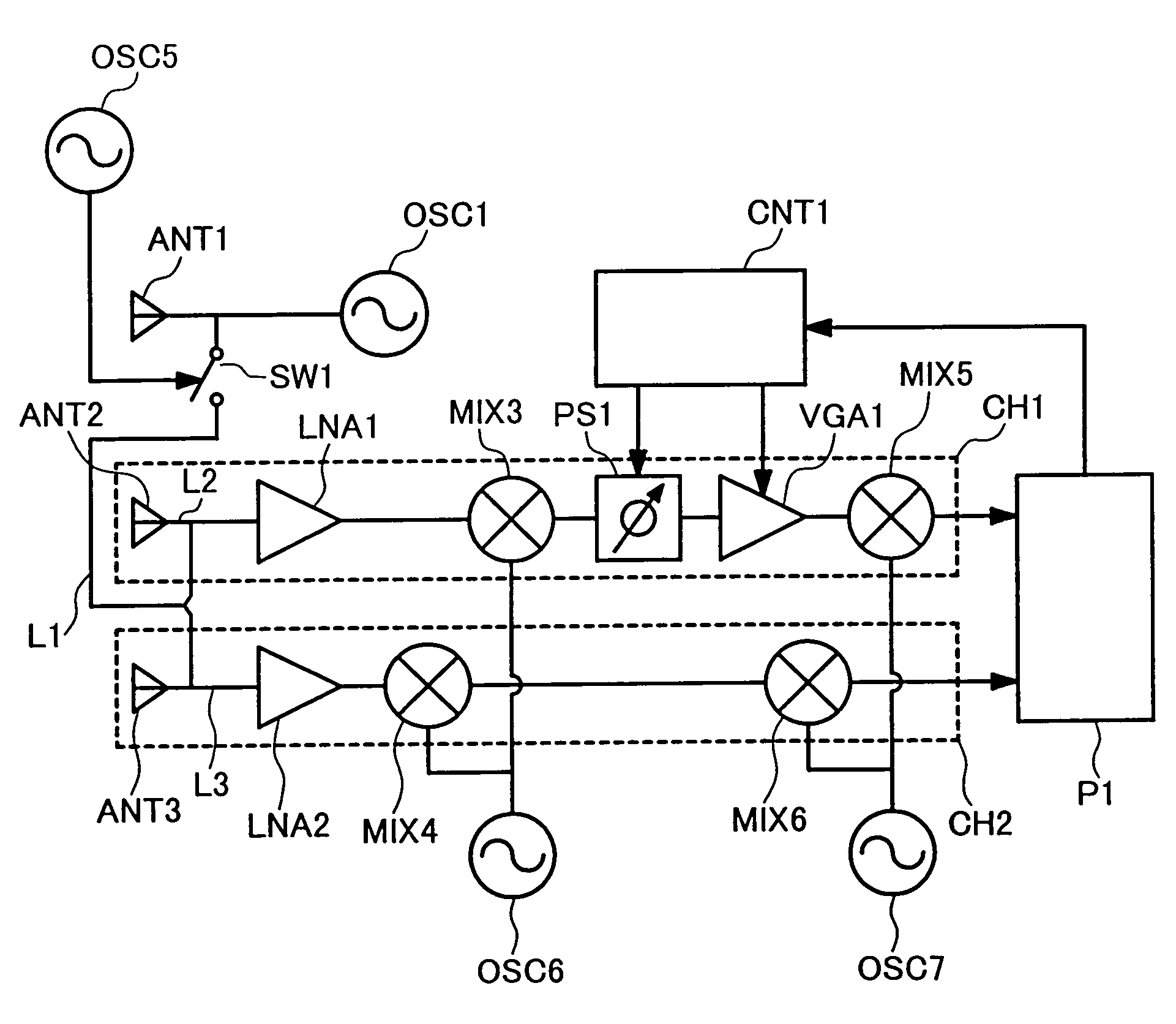
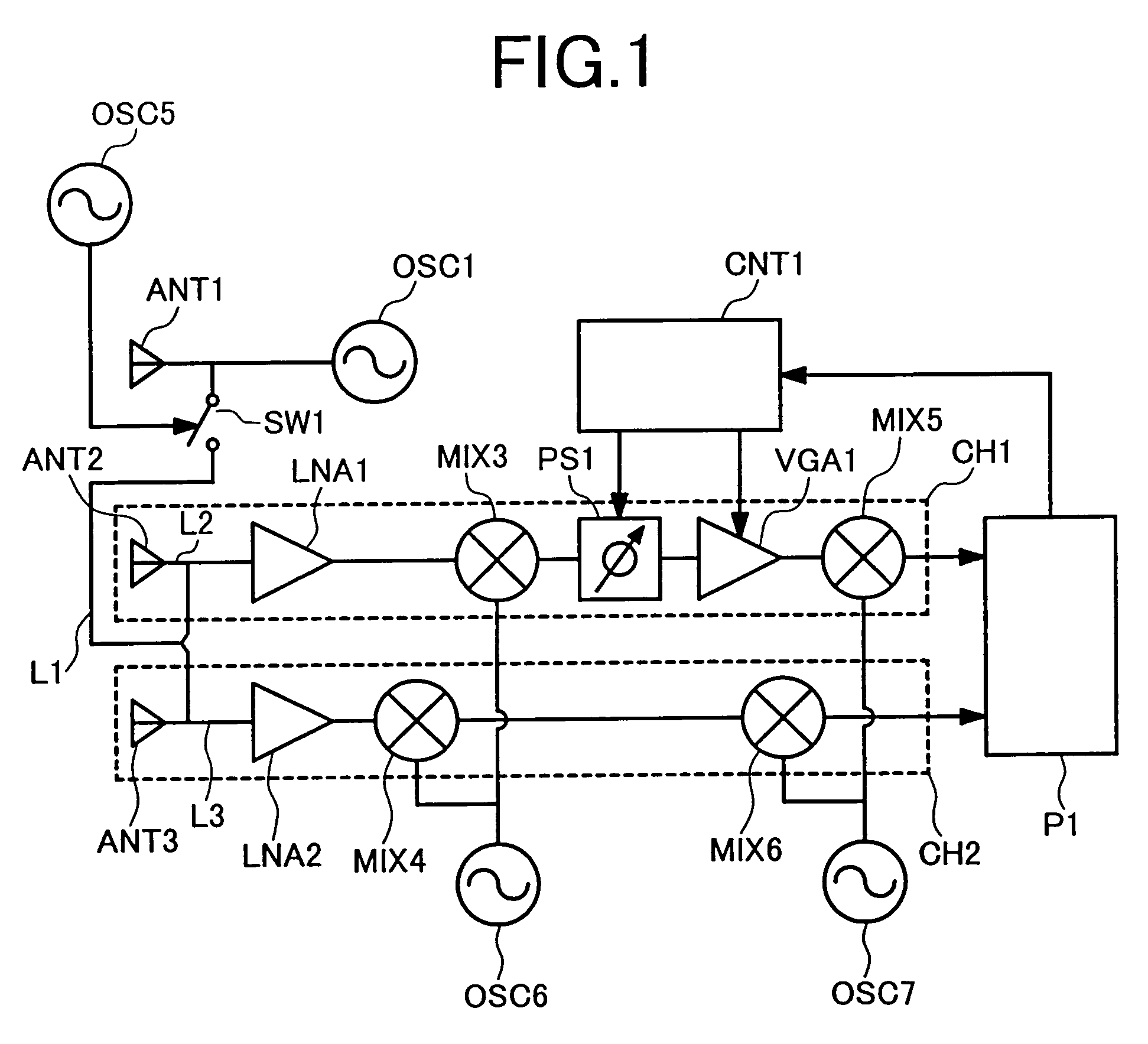
[0039]FIG. 1 is a block diagram showing a configuration of a first embodiment of a monopulse radar system according to the present invention. The present embodiment is a monopulse radar system which has a transmitting antenna ANT1, and two receiving antennas ANT2 and ANT3 and which radiates or emits a transmit signal from the transmitting antenna ANT1, receives a signal obtained by allowing the transmit signal to be reflected by a target, with the receiving antennas ANT2 and ANT3, and detects an azimuth angle of its target according to signal processing. The monopulse radar system includes a signal transmission line L1 for calibration connected from an oscillator OSC1 to the transmitting antenna ANT1, from which part of the transmit signal is supplied to each of signal transmission lines L2 and L3 connected to the receiving antennas ANT2 and ANT3 as a signal...


PUM


Abstract

The present invention provides that a monopulse radar system to correct an amplitude error and a phase error developed between receiving channels and improve the accuracy of a detected angle. A part of a transmit signal is supplied to respective channels on the receiving side through a signal transmission line for calibration. At this time, the gains of a variable phase shifter and a variable gain amplifier are adjusted so that an azimuth angle of a pseudo target, based on a signal for calibration, which is calculated by signal processing means, reaches a predetermined angle. In the monopulse radar system of the present invention, calibration work is simplified and an angular correction can be automated. The present monopulse radar system of the present invention is capable of coping even with variations in characteristic after product shipment due to environmental variations and time variations in parts characteristic.

Description

[0001]This application is a Continuation of non-provisional U.S. Application No. Ser. 10 / 227,306 filed Aug. 26, 2002 now U.S. Pat. No. 6,741,205. Priority is claimed based on U.S. application Ser. No. 10 / 227,306 filed Aug. 26, 2002, which claims the priority of Japanese Application No. 2002-050864 filed on Feb. 27, 2002.BACKGROUND OF THE INVENTION[0002]1. Field of the Invention[0003]The present invention relates to a monopulse radar system, and more specifically to a monopulse radar system for radiating a signal from a transmitting antenna, and receiving a signal reflected by a target with a plurality of receiving antennas to thereby detect an angle of an existing position of the target.[0004]2. Description of the Related Art[0005]In a radar system, a monopulse system is known as one method of detecting an azimuth angle to a target. The monopulse system radiates a signal from a transmitting antenna and receives a signal reflected by a target through the use of two or more receiving ...

Claims


Application Information

Patent Timeline
Patent Type & Authority Patents(United States)
IPC IPC(8): G01S7/40G01S13/44G01S13/00G01S7/02G01S7/03G01S13/931
CPCG01S7/032G01S7/4021G01S13/44G01S7/4052G01S7/4017G01S2013/9325G01S13/931G01S2007/4069G01S7/4069
Inventor NAGASAKU, TOSHIYUKI
Owner HITACHI LTD
Why Eureka
Try Eureka