Image forming apparatus

a technology of forming apparatus and rotating body, which is applied in the direction of couplings, instruments, electrographic processes, etc., can solve problems such as and achieve the effect of preventing fluctuation in rotational speed of rotating bodies

Inactive Publication Date: 2007-05-01
RICOH KK
View PDF61 Cites 109 Cited by
  • Summary
  • Abstract
  • Description
  • Claims
  • Application Information

AI Technical Summary

Benefits of technology

[0006]The present invention was devised with the foregoing problem in view, an object thereof being to provide a drive force transmission device and an image forming apparatus using same, which make it possible to prevent fluctuation in the rotational speed of rotating bodies caused by misalignment between the central axes of a driven side rotational coupling section for rotating a rotating body, such as a developer carrier, and a drive source side rotational coupling section for transmitting rotational drive force to the driven side rotational coupling section.

Problems solved by technology

However, misalignment of the central axes is liable to occur between the rotational coupling section on the driven side which causes the rotating body to rotate and the rotational coupling section on the drive source side which transmits rotational drive force to the rotational coupling section on the driven side, and hence there are problems to be resolved, such as fluctuation in the rotational speed of the rotating bodies caused by the aforementioned loss of central alignment.

Method used


Image

  • Image forming apparatus
  • Image forming apparatus
  • Image forming apparatus

Examples


Embodiment Construction

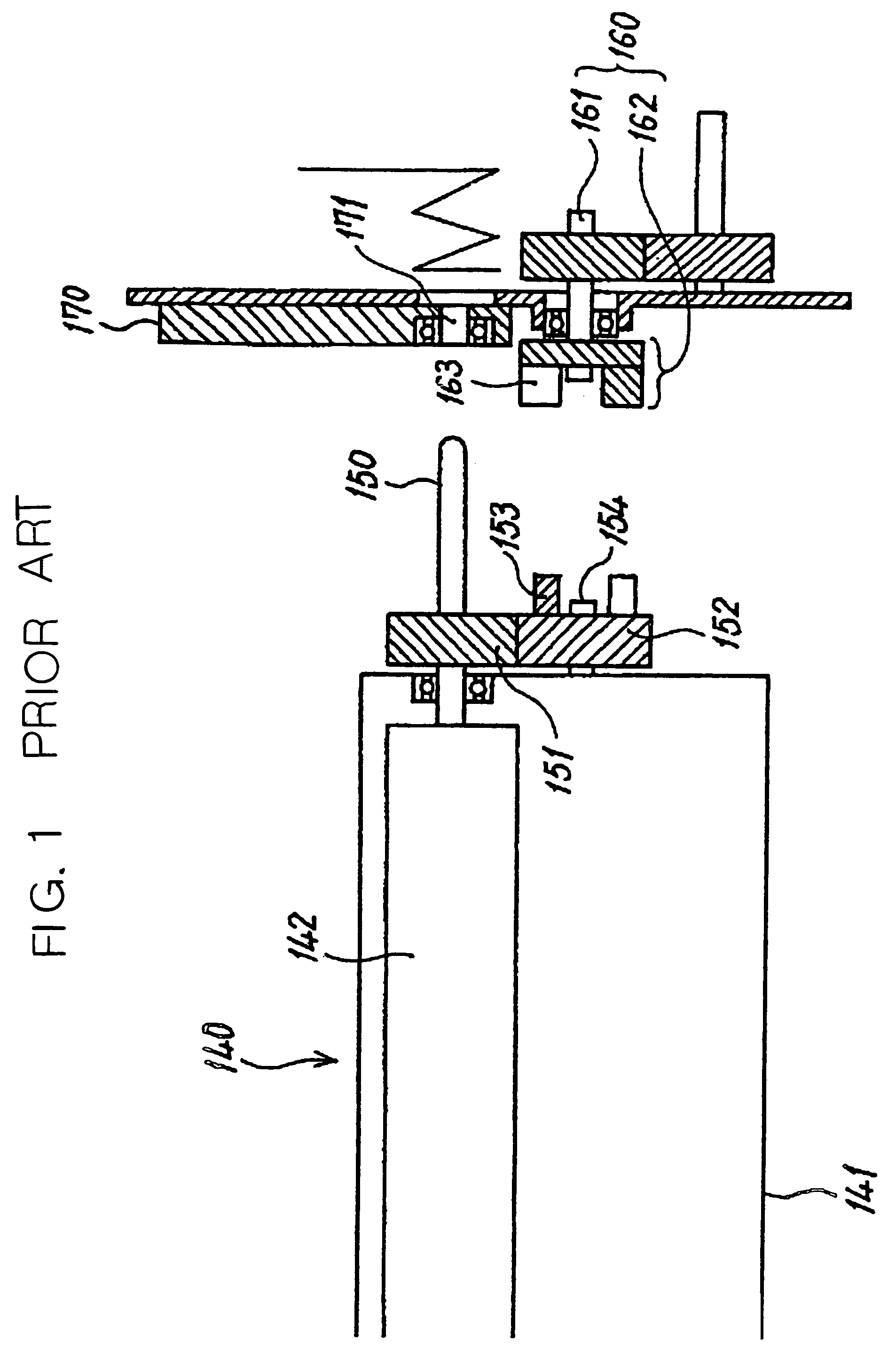
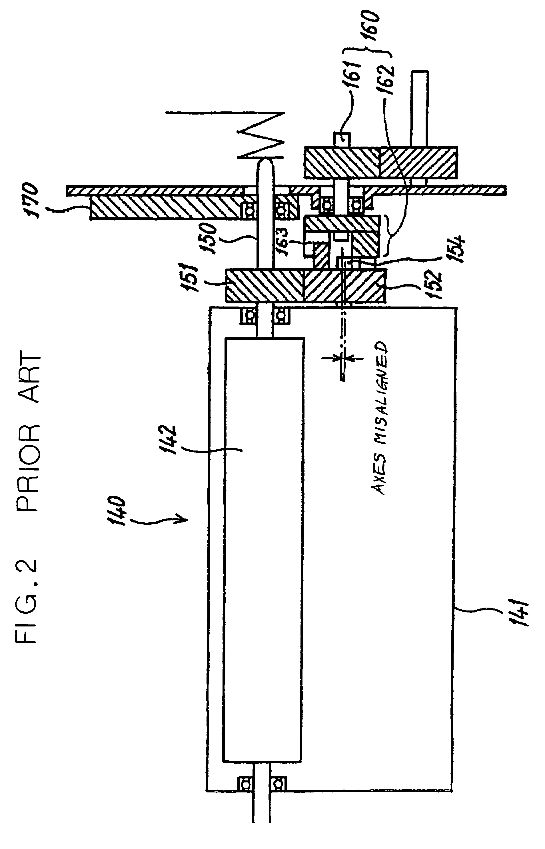
[0029]Before describing the present invention, the prior art and the problems associated with same will be described.

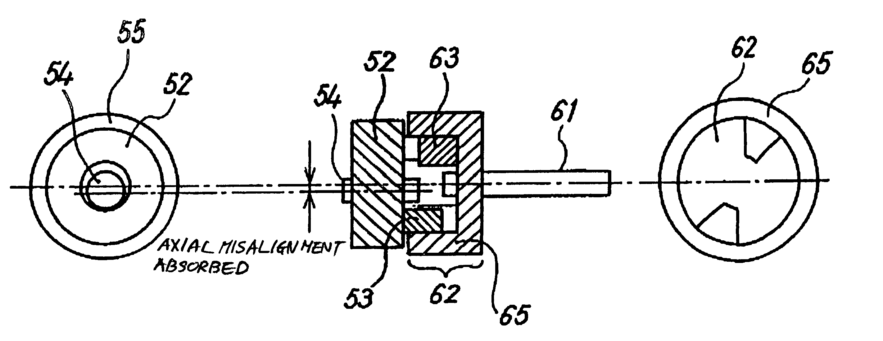
[0030]FIG. 1 and FIG. 2 show the composition of a developing device of a conventional image forming apparatus. As shown in these diagrams, the developing device 140 is constituted by a developing roller 142 forming a developer carrier disposed in such a manner that it is partially exposed from the opening of the casing 141, and a conveyance screw and developer ductor, and the like, which are not illustrated. A developing roller axle 150 extends from the interior of the casing 141, via the side face of the casing 141 (the right-hand side in the diagram), and a roller gear 151 is fixed to the developing roller axle 150 on the outer side of the casing 141. A coupling gear 152 supported rotatably on the side face of the casing 141 meshes with the roller gear 151. Two fingers 153 forming a projecting section are provided in a protruding manner on the end face of the coupli...


PUM


Abstract

An image forming apparatus whereby it is possible to prevent unevenness in developing density caused by misalignment between the central axes of a driven side rotational coupling section for rotating a developer carrier and a drive side rotational coupling section for transmitting rotational drive force to the driven side rotational coupling section. The driven side rotational coupling section is fixed and the position thereof can be corrected slightly, by engaging the driven side rotational coupling section with a drive side rotational coupling section. A transmission gear is provided which meshes with the driven side rotational coupling section and transmits rotational drive force used to move the surface of the developer carrier. By means of an axle provided on at least one end of the transmission gear engaging with a positioning member on the main body of the image forming apparatus, the developer carrier is positioned in the main body of the image forming apparatus.

Description

BACKGROUND OF THE INVENTION[0001]1. Field of the Invention[0002]The present invention relates to an image forming apparatus, such as a copying machine, a facsimile machine, a printer, having a latent image carrier, such as a photosensitive drum, for carrying a latent image on the surface thereof, and a developing device for developing the latent image into a visible image, provided with a developing agent carrier, such as a developing roller, for carrying an image forming material on the surface thereof. More particularly, the present invention relates to a drive force transmission device used in an image forming apparatus of this kind for receiving the rotational drive force of a drive source side and transmit this force to the driven side.[0003]2. Description of the Related Art[0004]Generally, in an image forming apparatus, such as a copying machine, facsimile machine, printer, or the like, many rotating bodies, such as a drum-shaped photosensitive body, a developing roller, and t...

Claims


Application Information

Patent Timeline
Patent Type & Authority Patents(United States)
IPC IPC(8): G03G15/06F16D3/04G03G15/08
CPCG03G15/0806G03G21/1647G03G21/1676G03G2221/1657
Inventor SUDO, KAZUHISASUGIHARA, KAZUYUKIYOSHIZAWA, HIDEOMASUDA, KATSUMIKIMURA, HIDEKISAKAI, KIYOTAKAIMAMURA, TSUYOSHI
Owner RICOH KK
Why Eureka
Try Eureka