Method of using a self-locking travel pattern to achieve calibration of remote sensors using conventionally collected data

a technology of self-locking travel pattern and remote sensor, which is applied in the field of vehicle mounted imaging, can solve the problems of insufficient information to obtain accurate records inferior geometric fidelity in image quality, and inability to obtain accurate data of the location of the sensor, so as to remove the bias in image output

Inactive Publication Date: 2007-05-01
VI TECH LLC
View PDF26 Cites 26 Cited by
  • Summary
  • Abstract
  • Description
  • Claims
  • Application Information

AI Technical Summary

Benefits of technology

[0008]The present invention provides a method of calibrating a remote sensing system employed in a vehicle, such as an aircraft, using remote sensing data collected during conventional vehicle operation. The method includes mounting at least one remote sensor on a vehicle and moving the vehicle in a self-locking pattern over a target area, the movement comprising any pattern that produces at least three substantially parallel travel lines out of a group of three or more lines, at least one of which travel lines is in an opposing direction to the other substantially parallel travel lines. Swath widths are generated for each substantially parallel travel line with the remote sensor device. Remote sensing data is collected of the target area during vehicle movement, which is inputted into a computer to calculate calibration data. The calibration data is applied to the remote sensing data to remove bias in image output.

Problems solved by technology

One drawback to using current airborne imaging techniques is the inferior geometric fidelity in image quality since the two-dimensional spatial images captured by the remote sensors are not acquired at the same instant.
Consequently, any changes in the direction of the aircraft's velocity or attitude results in geometric distortions for different regions within the two-dimensional image.
Also, sufficient information is not available to obtain accurate records of the sensor's location or its attitude parameters at the appropriate instant.
Therefore, the collected data requires sophisticated and expensive post-mission processing to improve upon the geometric fidelity and to achieve a positioning accuracy that meet the user's requirement.
Another drawback to current airborne imaging is that the remote sensors mounted to the aircraft have to be calibrated in order to accurately obtain the absolute geophysical coordinates of the remote sensing data.
No accurate absolute geophysical coordinate information, suitable for medium and large scale mapping applications, of any terrestrial features in an image scene is available on the original mission medium.
Panels made of cloth have been used as calibration targets but are expensive, difficult to handle, require intensive effort to lay out in a field, are easily damaged, and usually must be gathered up after the calibration exposure is completed.
In addition, deploying calibration targets requires significant labor costs when sites are remote or when images must be acquired frequently.

Method used


Image

  • Method of using a self-locking travel pattern to achieve calibration of remote sensors using conventionally collected data
  • Method of using a self-locking travel pattern to achieve calibration of remote sensors using conventionally collected data
  • Method of using a self-locking travel pattern to achieve calibration of remote sensors using conventionally collected data

Examples


Embodiment Construction

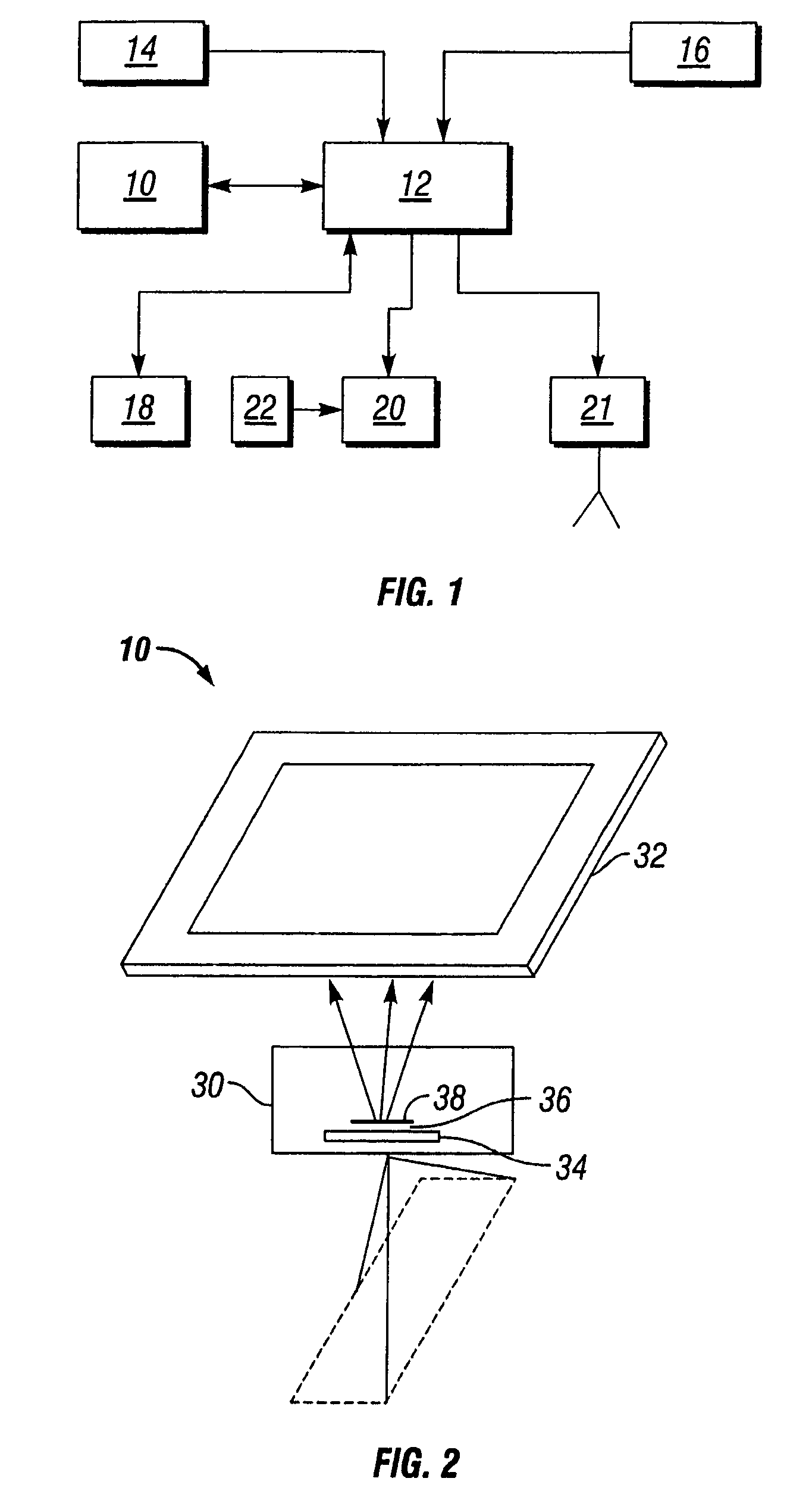
[0023]The present invention provides a method of calibrating remote sensors using remote sensing data collected during conventional operation of a vehicle. FIG. 1 depicts an aircraft on-board remote sensing system that can utilize a preferred embodiment of the method of the present invention. The on-board remote sensing system has at least one remote sensor device 10 that is designed to obtain data of a site flown over by an aircraft. The remote sensor device 10 is associated with a computer 12 suited to form, select and correct images of the site flown over. The computer 12 is connected to a positioning device 14 to allow continuous association of geographic data with the images acquired. The computer 12 can also be connected to an attitude-sensing device 16 whose indications allow readjustment of the images acquired according to the trajectory of the aircraft. The on-board system can further comprise a memory unit 18 and navigation guidance system 20 to provide immediate feedback ...


PUM


Abstract

The present invention provides a method to calibrate an on-board remote sensing system using a self-locking travel pattern and target remote sensing data. The self-locking travel pattern includes a number of parallel travel lines having overlapping swath widths between adjacent travel lines. The overlapping swath widths are used to determine the boresight angles and range offset of the remote sensor device. In addition, the method can be used to generate estimated horizontal and vertical displacement errors. These estimated errors can be used as correction factors for the range offset and boresight angles.

Description

FIELD OF THE INVENTION[0001]This invention relates generally to the field of imaging using remote sensors. More specifically, this invention relates to a method of calibrating a vehicle-mounted remote sensor device using remote sensing data collected during conventional operation of the vehicle.BACKGROUND OF THE INVENTION[0002]Remote sensing involves the acquisition of information or data around a distant object or system without being in physical contact with it. Most remote sensing instruments are designed to analyze the characteristics of the electromagnetic spectra reflected by objects (their spectral signatures) to allow one to determine some of the objects' properties. Human vision uses the same principle when using color (the sensation produced when light of different wavelengths falls on the human eye) to identify objects. The sensors used in remote sensing, however, make it possible to broaden the field of analysis to include parts of the electromagnetic spectrum that are w...

Claims


Application Information

Patent Timeline
Patent Type & Authority Patents(United States)
IPC IPC(8): G01C19/00G01CG01C11/00G01C25/00G01D18/00G01S7/497G06F19/00
CPCG01C11/00G01C25/00G01S7/497
Inventor MAI, TUY VU
Owner VI TECH LLC
Why Eureka
Try Eureka