Pneumatic suspension and damping arrangement

a technology of pneumatic which is applied in the direction of shock absorbers, mechanical equipment, transportation and packaging, etc., can solve the problems of increasing the installation space requirement, undesirable friction between the guiding elements and the piston rod, and the relative position of the suspension and damping arrangement of the end fixed to the chassis with respect to the end fixed to the wheel, etc., to achieve the effect of reducing the number of components, maximizing comfort, and saving installation spa

Inactive Publication Date: 2007-05-08
CONTINENTAL AG
View PDF9 Cites 37 Cited by
  • Summary
  • Abstract
  • Description
  • Claims
  • Application Information

AI Technical Summary

Benefits of technology

[0007]To install the suspension and damping arrangement in a vehicle, the first (upper) air spring is connected, for example, via an upper cover, to the chassis of the vehicle, whereas the second (lower) air spring is connected via a cover to a mounting element and is connected to the wheel mount of the vehicle. How this takes place will be explained step by step further below. When the first air spring rolls off over the second air spring, the two air springs must not necessarily make contact. The second air spring can almost dip into the first air spring when this first air spring rolls off over the second air spring, without the two air springs making contact. The advantage obtained with the invention is especially seen in that the arrangement of the air springs according to the invention can be built very short and compact and has no friction, because a shock absorber, which is usual in conventional suspension and damping arrangements, can be omitted. The attachment points of the upper cover and the mounting elements are advantageously configured in such a way that a conventional suspension and damping arrangement can be substituted with the suspension and damping arrangement according to the invention without great constructive modifications at the wheel mount or the vehicle body. Another advantage of the invention is that no undesirable friction especially by transverse forces is produced, which has an acoustically positive effect. The suspension and damping characteristics of the suspension and damping arrangement of the invention are therefore free of undesirable friction effects.
[0008]According to a further embodiment of the invention, a lower bell forms the outer contour of the lower flexible member of the second air spring and the roll-off contour of the upper flexible member of the first air spring. The comfort of a pneumatic suspension and damping arrangement depends essentially on the roll-off contour and the thickness of a flexible member. It is an advantage of the embodiment that the roll-off contour of the upper flexible member of the first air spring can be freely selected via the outer shaping of the lower bell and can thus be adjusted to an optimum comfort. Another advantage of this embodiment is that the outer guide contour of the lower flexible member of the second air spring allows a reduction of the thickness of this lower rolling lobe to an amount which is ideal for the comfort of the suspension and damping arrangement. Advantageously, the contour of the inner surface of the lower bell (outer guide contour of the lower flexible member of the second air spring) can be freely selected independently of the outer shape of the lower bell (roll-off contour of the upper flexible member of the lower air spring) and thus can be adapted optimally to the comfort of the suspension and damping arrangement.
[0009]According to a further embodiment of the invention, the lower bell is connected to the mounting element. This mounting element makes possible the connection of the suspension and damping arrangement of the invention to a conventional wheel mount of a vehicle. For this reason, no complex structural changes are necessary on the wheel mount of a vehicle for the installation of the suspension and damping arrangement of the invention.
[0010]According to a further embodiment of the invention, an upper bell represents an outer guide contour of the upper flexible member of the first air spring. The advantage of this embodiment is seen in that the outer guide contour of the upper flexible member of the first air spring allows a reduction of the thickness of this upper flexible member to an amount which is ideal for the comfort of the suspension and damping arrangement and permits a free shaping of this outer contour for an optimum comfort.
[0011]According to a further embodiment of the invention, a lower roll-off piston of the second air spring (which predefines the roll-off contour thereof) is connected to the upper bell. With this arrangement, in comparison with a conventional suspension and damping arrangement, a shock absorber can be omitted which is used conventionally for accommodating and attaching the piston of an air spring and connects the upper cover to the lower roll-off piston of the second air spring.
[0012]Another advantage of this embodiment is that both air springs can be orientated in the same direction and this saves installation space.

Problems solved by technology

The pivotability of the suspension and damping arrangement of the end fixed to the chassis with respect to the end fixed to the wheel is relatively low since the pivot bearing of the suspension and damping arrangement cannot be configured as soft and elastic as desired.
Furthermore, an undesirable friction occurs between these guiding elements and the piston rod, especially if additional transverse forces are present.
This embodiment of a suspension and damping arrangement with the housing having an H-shaped cross section leads to a complex configuration of the wheel mount, especially the fixed connection to the vehicle, and to an increased installation space requirement.
This suspension and damping arrangement therefore cannot replace the conventional suspension and damping arrangements without special adaptations on the vehicle body with reference to the wheel mount, the fixed connection to the vehicle body and the installation space.

Method used


Image

  • Pneumatic suspension and damping arrangement
  • Pneumatic suspension and damping arrangement
  • Pneumatic suspension and damping arrangement

Examples


Embodiment Construction

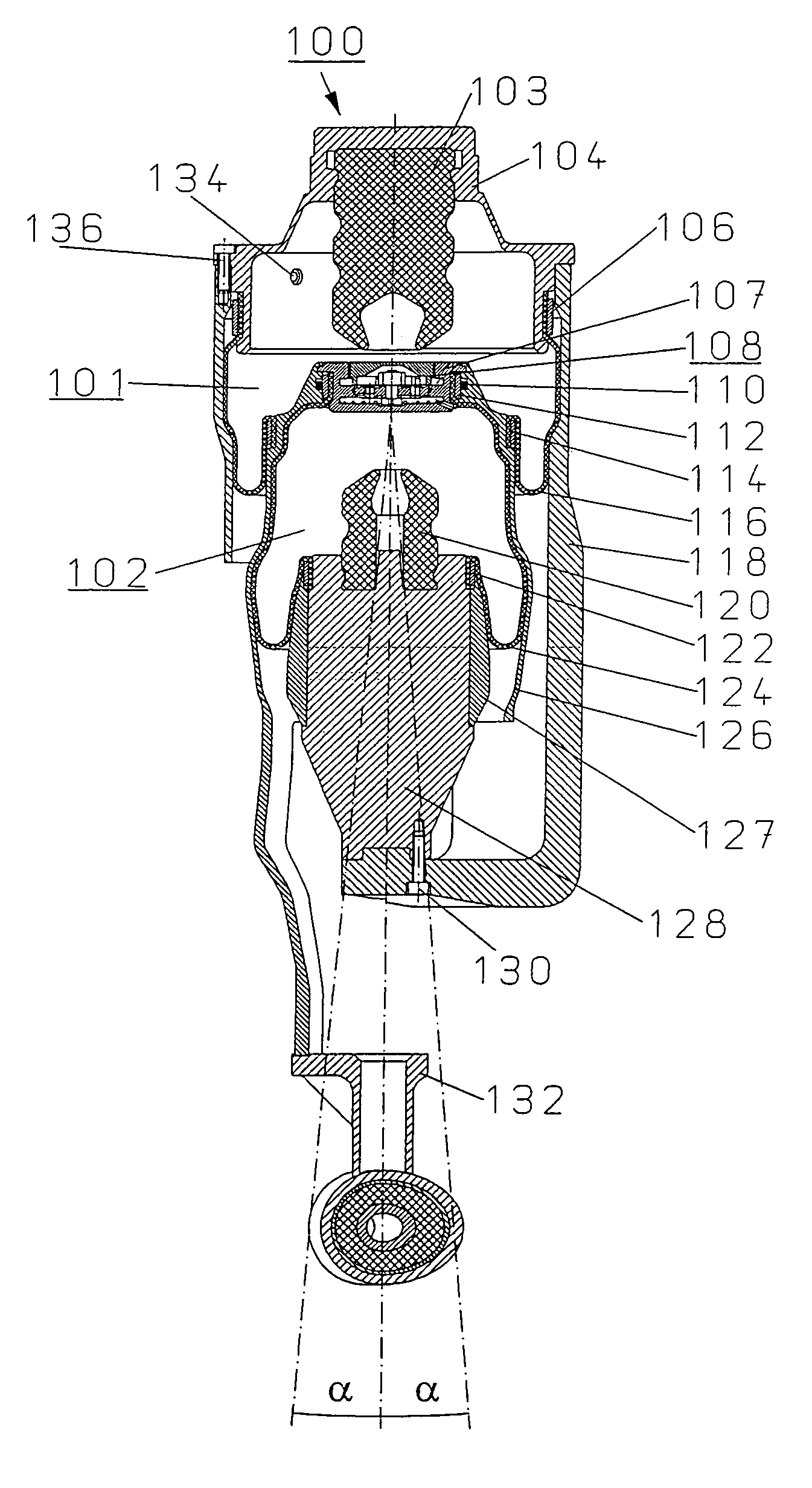
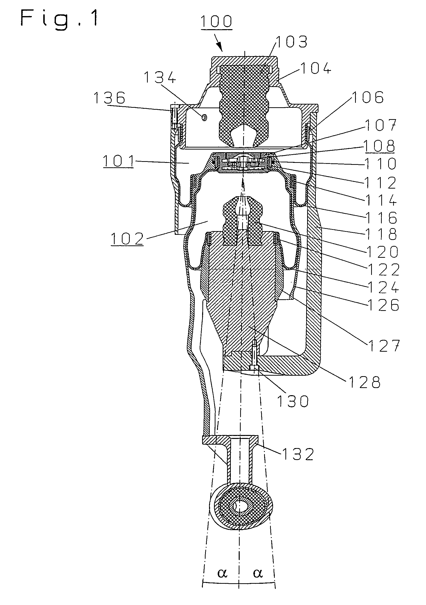
[0039]FIG. 1 shows a suspension and damping arrangement having a first air spring 101 and a second air spring 102. The first air spring 101 is hermetically sealed to the outside via a flexible member 116 and rolls off forming a rolling lobe above the second air spring 102, which is also hermetically sealed to the outside via a flexible member 124. The two air springs (101, 102) are connected via a throttle element 108, through which air can flow in both directions. The throttle element 108 has one or several through-bores with one or several check valves per throughflow direction and determines therewith the possible damping performance of the suspension and damping arrangement 100.

[0040]The upper end of the flexible member 116 of the first air spring 101 is tightly connected via a clamp ring 106 to an upper cover 104 which comprises an ancillary spring 103 and an air connection 134. When the first air spring 101 is almost completely deflected, the ancillary spring 103 is supported ...


PUM


Abstract

A pneumatic suspension and damping arrangement (100) is fixedly mounted on the chassis at the upper region and to the wheel mount at the lower region thereof. The arrangement includes two hermetically closed air springs (101, 102) filled with pressurized gas, whose volumes can be changed and which are connected via an air connection (134) to a pressurized gas source. The air springs are each enclosed by a movable wall formed by a flexible member (116, 124) and each roll off on a roll-off contour and are connected to each other via a throttle element (108) through which the gas can flow in two directions. The air springs are arranged one above the other and the roll-off contour of the first air spring (101) is defined in such a way by the second air spring (102) that the first air spring (101) rolls off on the second air spring (102). A connecting element of the upper cover (104) ) with the roll-off piston (128) of the second air spring (102) runs outside of the two air springs (101, 102).

Description

FIELD OF THE INVENTION[0001]The invention relates to a pneumatic suspension and damping arrangement, especially for vehicles, which can preferably be fixedly mounted on the chassis in the upper area and to a wheel mount in the lower area. The pneumatic suspension and damping arrangement includes at least two hermetically closed air springs filled with compressed gas, whose volumes can be changed and which can be connected via an air connection to a compressed gas source. The air springs each include a movable wall formed by a flexible member and roll off on a roll-off contour and are connected via a throttle element through which a fluid such as air can flow in two directions. The air springs are arranged one above the other and the roll-off contour of the first air spring is predefined in such a way by the second air spring that the first air spring rolls off above the second air spring. An upper cover of the first air spring is connected via a connecting element to a roll-off pist...

Claims


Application Information

Patent Timeline
Patent Type & Authority Patents(United States)
IPC IPC(8): F16F9/04B60G11/26B60G17/052F16F9/05F16F9/32F16J3/04
CPCB60G17/0521F16F9/0454F16F9/0472F16F9/05F16F9/055
Inventor BEHMENBURG, CHRISTOFJOB, HEINZMARTENS, MICHAELHARTEL, VOLKERHUBER, GERALDKILSCH, ARMINENGELKE, THOMASKOTT, BURKHARD
Owner CONTINENTAL AG
Why Eureka
Try Eureka