Lighting device and lighting method

a technology of lighting device and lighting method, which is applied in the direction of lighting support device, discharge tube luminescnet screen, instruments, etc., can solve the problems of significant deficiency in green, poor color rendering, and particularity deficient in red color rendering, so as to reduce the efficiency of such systems and achieve low efficiency. , the effect of high efficiency

Active Publication Date: 2007-05-08
IDEAL IND LIGHTING LLC
View PDF24 Cites 1596 Cited by
  • Summary
  • Abstract
  • Description
  • Claims
  • Application Information

AI Technical Summary

Benefits of technology

[0036]Employing LEDs having a wide variety of hues would similarly necessitate use of LEDs having a variety of efficiencies, including some with low efficiency, thereby reducing the efficiency of such systems.
[0037]There is therefore a need for a high efficiency white light source that combines the efficiency and long life of white LEDs (i.e., which avoids the use of relatively inefficient light sources) with an acceptable color temperature and good color rendering index and a wide gamut.

Problems solved by technology

There exist “white” LED light sources which are relatively efficient but which have poor color rendering, typically having CRI values of less than 75, and which are particularity deficient in the rendering of red colors and also to a significant extent deficient in green.
Such lamps, therefore, are considered to provide poor color rendition, particularly when illuminating various settings such as a theater stage, television set, building interior, or display window.
In addition, currently available green LEDs are relatively inefficient, and thus limit the efficiency of such lamps.
Employing LEDs having a wide variety of hues would similarly necessitate use of LEDs having a variety of efficiencies, including some with low efficiency, thereby reducing the efficiency of such systems.

Method used


Image

  • Lighting device and lighting method
  • Lighting device and lighting method
  • Lighting device and lighting method

Examples


Embodiment Construction

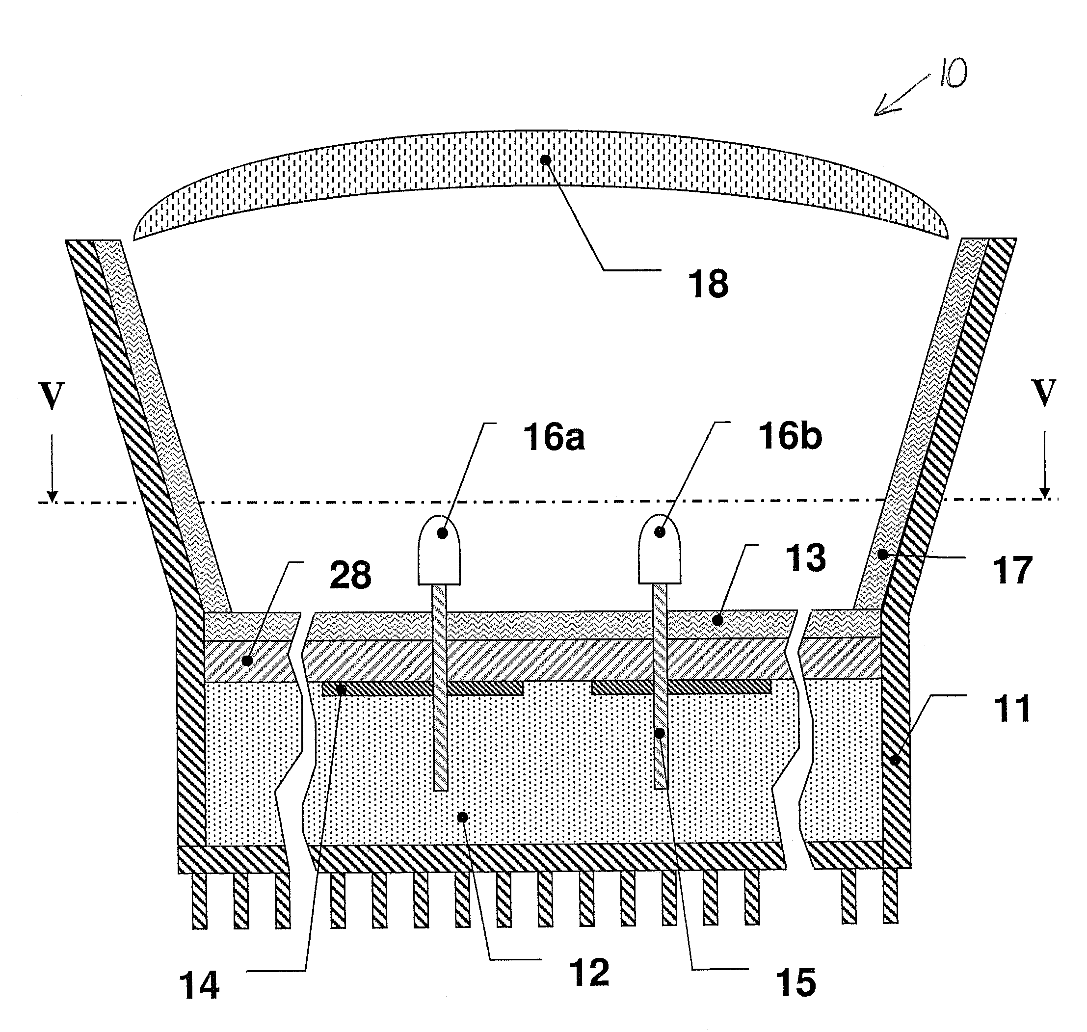
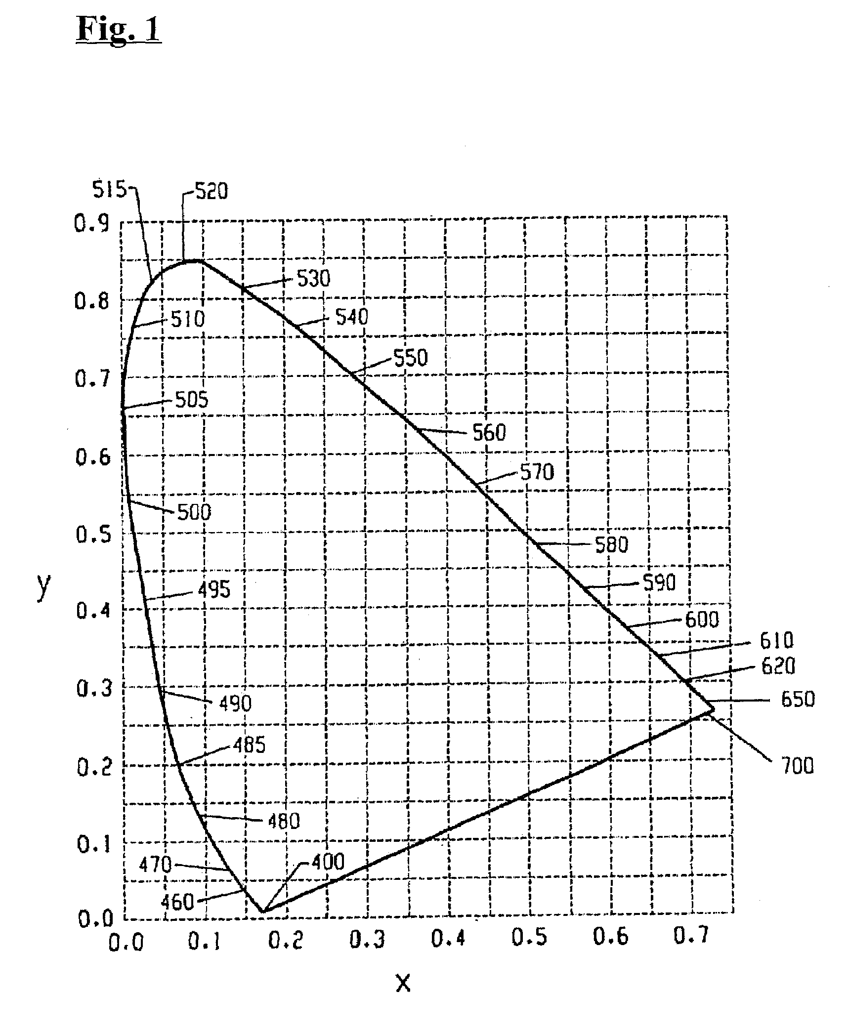
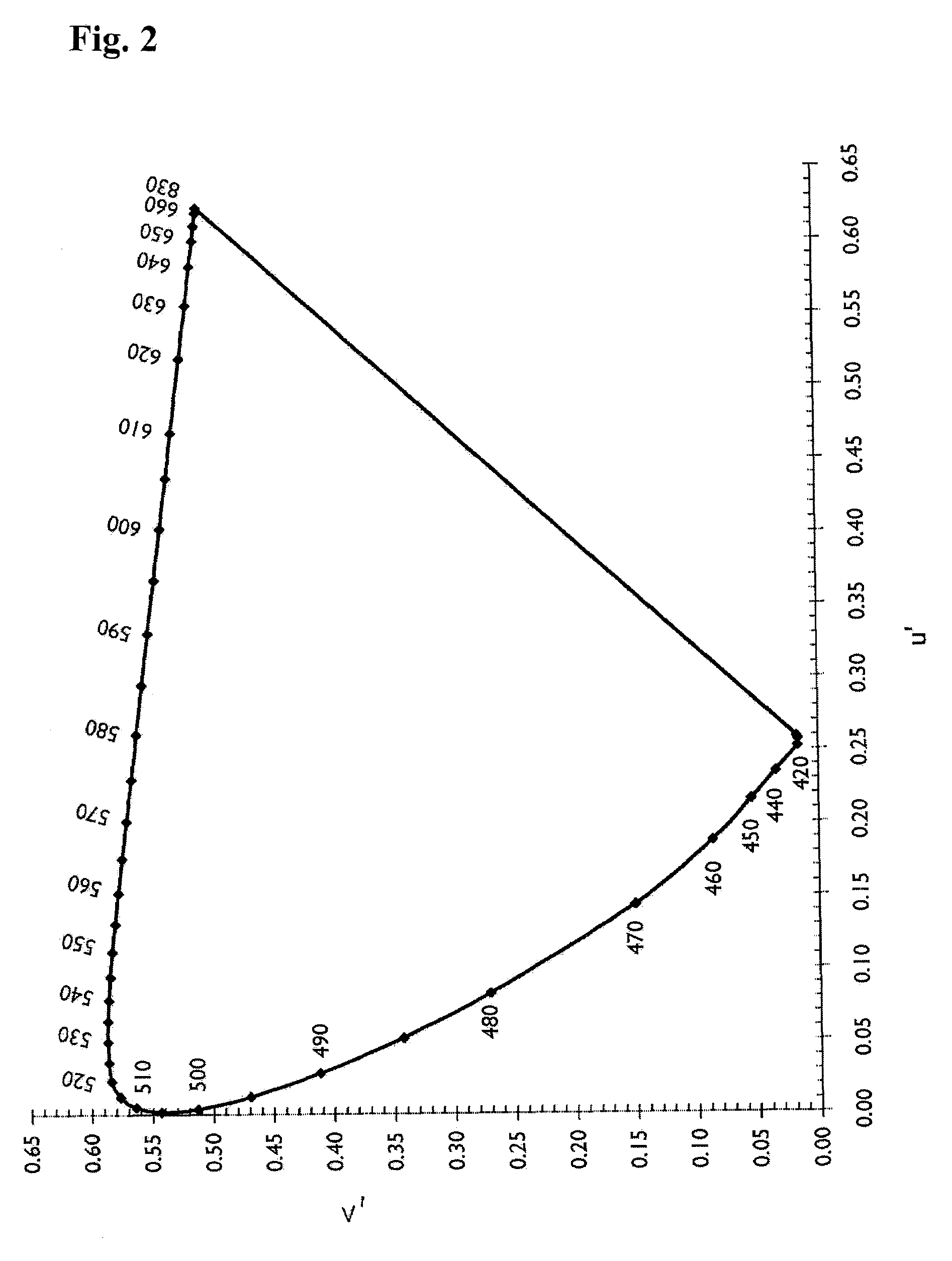
[0108]The expression “430 nm to 480 nm solid state light emitter” means any solid state light emitter which, if illuminated, would emit light having a dominant wavelength in the range of from about 430 nm to about 480 nm.

[0109]The expression “555 nm to 585 nm lumiphor” means any lumiphor which, if excited, would emit light having a dominant wavelength in the range of from about 555 nm to about 585 nm.

[0110]The expression “600 nm to 630 nm solid state light emitter” means any solid state light emitter which, if illuminated, would emit light having a dominant wavelength in the range of from about 600 nm to about 630 nm.

[0111]The term “current”, as used in the expression “if current is supplied to the first power line” means electrical current which is sufficient to cause the 430 nm to 480 nm solid state light emitter(s) to emit light having a dominant wavelength in the range of from about 430 nm to about 480 nm, to cause the 555 nm to 585 nm lumiphor(s) to emit light having a dominant...


PUM


Abstract

A lighting device comprising first and second groups of solid state light emitters, which emit light having dominant wavelength in ranges of from 430 nm to 480 nm and from 600 nm to 630 nm, respectively, and a first group of lumiphors which emit light having dominant wavelength in the range of from 555 nm to 585 nm. If current is supplied to a power line, a combination of (1) light exiting the lighting device which was emitted by the first group of emitters, and (2) light exiting the lighting device which was emitted by the first group of lumiphors would, in an absence of any additional light, produce a sub-mixture of light having x, y color coordinates within an area on a 1931 CIE Chromaticity Diagram defined by points having coordinates (0.32, 0.40), (0.36, 0.48), (0.43, 0.45), (0.42, 0.42), (0.36, 0.38). Also provided is a method of lighting.

Description

CROSS-REFERENCE TO RELATED APPLICATIONS[0001]This application claims the benefit of U.S. Provisional Patent Application No. 60 / 752,555, filed Dec. 21, 2005, entitled “Lighting Device and Lighting Method” (inventors: Antony Paul van de Ven and Gerald H. Negley), the entirety of which is hereby incorporated by reference.[0002]This application claims the benefit of U.S. Provisional Patent Application No. 60 / 752,556, filed on Dec. 21, 2005, entitled “SIGN AND METHOD FOR LIGHTING” (inventors: Gerald H. Negley and Antony Paul van de Ven), the entirety of which is hereby incorporated by reference.[0003]This application claims the benefit of U.S. Provisional Patent Application No. 60 / 792,859, filed on Apr. 18, 2006, entitled “LIGHTING DEVICE AND LIGHTING METHOD” (inventors: Gerald H. Negley and Antony Paul van de Ven), the entirety of which is hereby incorporated by reference.[0004]This application claims the benefit of U.S. Provisional Patent Application No. 60 / 793,524, filed on Apr. 20, 2...

Claims


Application Information

Patent Timeline
Patent Type & Authority Patents(United States)
IPC IPC(8): F21V9/00
CPCH05B33/0803H05B33/0857H05B33/0827F21K9/00F21Y2105/001H01L2924/01047F21Y2101/02H01L2224/48091H01L2924/15747H01L2224/45147H01L2924/13091H01L2924/01015H01L2224/48247H01L2924/00014H01L2924/00F21Y2105/10F21Y2115/10H01L2924/00011F21K9/62H05B45/46H05B45/20H05B45/30H01L2924/01005H01L2924/01032
Inventor VAN DE VEN, ANTONY PAULNEGLEY, GERALD H.
Owner IDEAL IND LIGHTING LLC
Why Eureka
Try Eureka